Shutdown cooling pump vortex detection system

A shutdown cooling and coolant technology, applied to reactors, nuclear reactor monitoring, greenhouse gas reduction, etc., can solve impossible problems

Inactive Publication Date: 2000-10-04
ABB COMBUSTION ENG NUCLEAR POWER
View PDF1 Cites 3 Cited by
  • Summary
  • Abstract
  • Description
  • Claims
  • Application Information

AI Technical Summary

Problems solved by technology

Shutdown cooling pump flow measurement alarm only occurs after air has been sucked into the pump and therefore cannot be used to avoid air turbulence

Method used


Image

  • Shutdown cooling pump vortex detection system
  • Shutdown cooling pump vortex detection system
  • Shutdown cooling pump vortex detection system

Examples


Embodiment Construction

[0023] Detailed description of the preferred embodiment

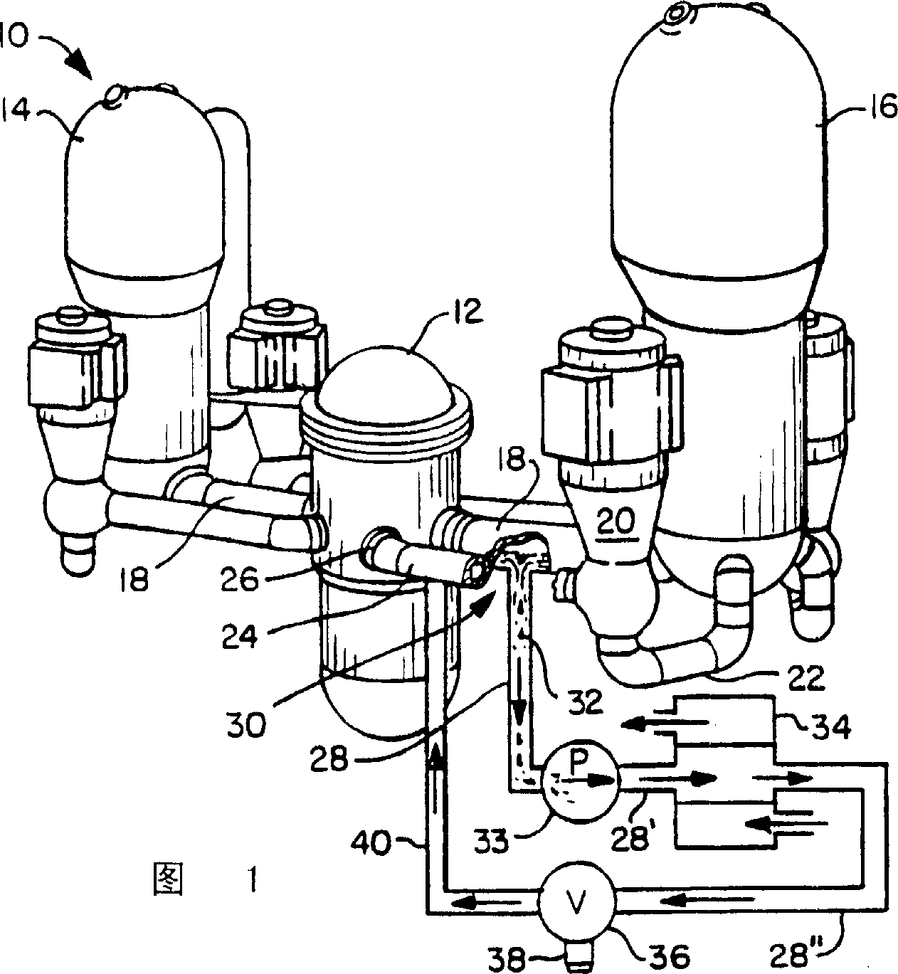
[0024] Shown in Fig. 1 is to have added a nuclear power plant of the present invention. Reference numeral 10 generally designates a nuclear power plant of the pressurized water reactor type in which water is continuously conveyed through a closed circulation loop between the reactor 12 and each of the two steam generators 14 and 16, respectively.

[0025] Water coolant from reactor 12 flows through main pipe or heat pipe section 18 to steam generators 14 and 16, with similar piping for each heat exchanger.

[0026] For purposes of illustration, with respect to steam generator 16 , cooling system circulation pump 20 circulates water that has been cooled in the steam generator through suction line section 22 and back to reactor 12 via cooling line section 24 and inlet 26 .

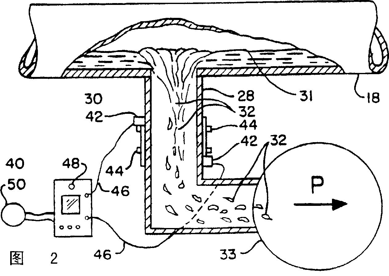
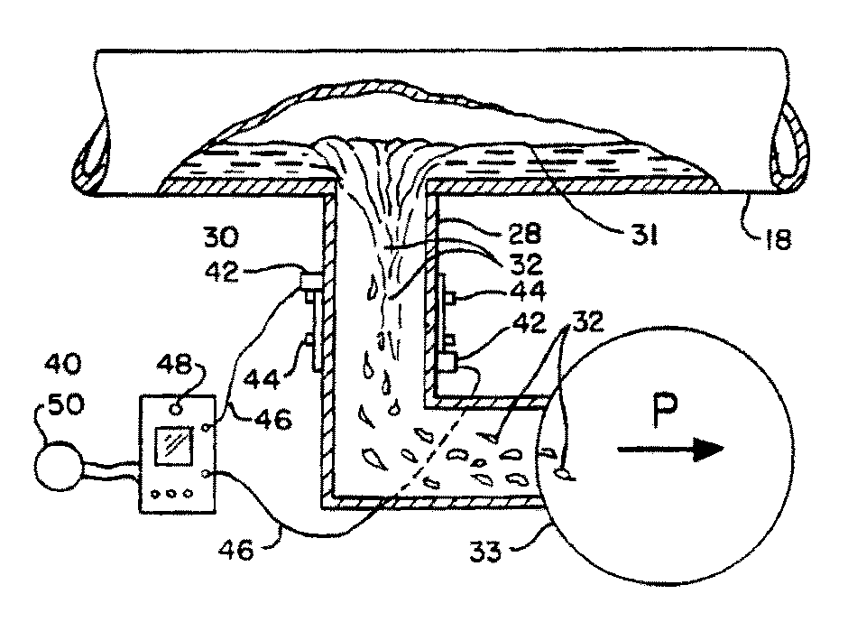
[0027] The shutdown cooling system drain pipe 28 intersects the lower region of the substantially horizontal main or heat pipe section 18 . In this...


PUM


Abstract

A system and method of detecting air vortexing and coriolis effect vortex-created cavitation in a shutdown cooling system drain pump (32) of a nuclear power plant during midloop operation where the plant includes a horizontal hot leg (18) having a drain pipe (28) connected from the lower region thereof to a drain pump (33) which includes attaching transducers (42) of a portable clamp-on ultrasonic flowmeter to the drain pipe (28) to measure and detect flow-void-created disruptions in the flowmeter ultrasonic signal and providing a remote alarm triggered by the disrupted signal.

Description

field of invention [0001] The present invention relates to a system and method for detecting air vortices in a drain pump of a shutdown cooling system of a nuclear power plant and cavitation caused by the Coriolis effect. background of the invention [0002] In nuclear power plants of the pressurized water reactor (PWR) type, a coolant liquid, essentially boron and water, is conveyed continuously through a closed circulation loop between the nuclear reactor and one or more steam generators. [0003] During power generation, the pressurized coolant absorbs heat released by thermonuclear reactions taking place in the reactor. The heated coolant then flows through a main pipe, aptly referred to as the "hot leg" of the circulation loop. The heat pipe section transfers hot coolant to the steam generator. [0004] In the steam generator, the coolant fluid is circulated through a heat exchanger. A heat exchanger cools the coolant fluid and utilizes the heat rejected from the coo...

Claims


Application Information

Patent Timeline
Patent Type & Authority Applications(China)
IPC IPC(8): G21C17/022
CPCG21Y2004/30G21Y2002/502G21Y2002/207G21C17/022Y02E30/30
Inventor R·P·哈维
Owner ABB COMBUSTION ENG NUCLEAR POWER
Why Eureka
Try Eureka