Method of data transmission, system for data transmission, control device for data transmission, and program recording medium

A data transmission and data technology, applied in the fields of data transmission, data transmission systems, data transmission control devices and program recording media, can solve the problems of high efficiency, excessive processing time, and poor efficiency.

Inactive Publication Date: 2000-11-01
PANASONIC CORP
View PDF0 Cites 1 Cited by
  • Summary
  • Abstract
  • Description
  • Claims
  • Application Information

AI Technical Summary

Problems solved by technology

[0017] Specifically, as explained above, there is a problem in the network configuration of the third control device (personal computer 105) shown in FIG. When the data transfer method of "a device issues a command to another device to transmit or receive data" as shown transfers still image data, the system becomes less efficient as described above, and the processing time exceeds the necessary range
[0018] Moreover, even when the improved data transmission method shown in the conventional FIG. 20 is adopted, there is still a problem that the processing when an error occurs is not efficient as described above, and the one-to-one connection shown in FIG. 19 and the like needs to be supported. The processing system used at the time and the different command processing system, the software installed on the device is unnecessarily large and too complicated

Method used


Image

  • Method of data transmission, system for data transmission, control device for data transmission, and program recording medium
  • Method of data transmission, system for data transmission, control device for data transmission, and program recording medium
  • Method of data transmission, system for data transmission, control device for data transmission, and program recording medium

Examples


no. 1 example

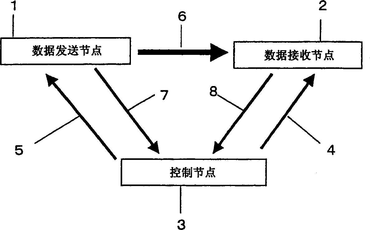
[0109] FIG. 1 is a block diagram of a data transmission system according to a first embodiment of the data transmission method of the present invention. In Fig. 1, 1 is the data sending node (first node) of sending image equipment such as digital still camera, 2 is the data receiving node (second node) of receiving image equipment such as printer, 3 is control node such as personal computer, set-top box, These devices are connected to the same bus system. Also, the data transfer control device of the present invention corresponds to the control node 3 .

[0110] This embodiment is described by taking the case where the bus system adopts IEEE standard 1394-1995 (ie high-performance serial bus standard) (hereinafter referred to as IEEE 1394-1995) to transmit data between connected devices.

[0111] In addition, 4 represents the data receiving command sent by the control node 3 to the data receiving node 2, 5 represents the data sending command sent by the control node 3 to the ...

no. 2 example

[0163] Next, a second embodiment of the present invention will be described. Fig. 5 is a block diagram of the system of the second embodiment of the data transmission method of the present invention. In addition, this embodiment is basically the same as the first embodiment shown in FIG. 1 , so detailed descriptions of system components and their operations are omitted.

[0164] The second embodiment shown in FIG. 5 differs from the previously described first embodiment in that the control node 3 is the same node as the data sending node 1 .

[0165] In Fig. 5, the data sending command 5 and the data sending command reply 7 shown in Fig. 1 are sent and processed inside the same node, so the above-mentioned packet data is not sent on the bus.

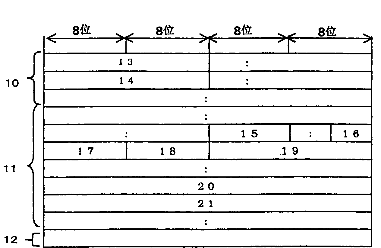
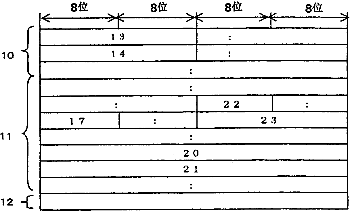
[0166] On the other hand, the data receiving command 4 issued to the data receiving node 2 takes exactly the same packet form as that of the case of the first embodiment illustrated in FIG. 3 . Here, the first embodiment differs from t...

no. 3 example

[0169] Next, a third embodiment of the present invention will be described. Fig. 6 is a block diagram of the system of the third embodiment of the data transmission method of the present invention. In addition, this embodiment is basically the same as the first embodiment shown in FIG. 1 , so detailed descriptions of system components and their operations are omitted.

[0170] The third embodiment shown in FIG. 6 is different from the previously described first embodiment in that the control node 3 is the same node as the data receiving node 2 .

[0171] In FIG. 6, for the data reception command 4 and the data reception command reply 8 shown in FIG. 1, these packet data are not sent on the bus due to internal processing.

[0172] On the other hand, the data reception command 5 issued to the data sending node 1 takes the exact same packet form as that of the case of the first embodiment illustrated in FIG. 2 . Here, the first embodiment differs from the present embodiment onl...


PUM


Abstract

A data transmission method in which data divided into N blocks (N is a natural number) are transmitted from a first node to a second node on a bus system where a node identifier is allocated to each node. Before transmitting the data blocks, the control node provides the second node with a data block reception instruction including the node identifier of the first node, and provides the first node with a data block transmission instruction including the node identifier of the second node. After that, the data blocks are forwarded from the first node to the second node. After the completion of forwarding the data block, the first node notifies the control node about the result of execution of the transmission of the data blocks, while the second node notifies the control node about the result of execution of the reception of the data blocks.

Description

technical field [0001] The present invention relates to a data transmission method, a data transmission system, a data transmission control device and a program recording medium for transmitting still image data, text data, and other data that do not require real-time processing between a plurality of devices. Background technique [0002] In recent years, the market for still image processing devices such as digital still cameras and printers has been expanding. These devices have traditionally been used in environments where existing personal computers exist, but in recent years there has been an increasing demand for easy disposal of these devices in environments without computers. [0003] Conventionally, when sending and receiving data that does not require real-time processing, represented by the above-mentioned still images and text data, between two devices, one device usually issues a command to the other device to transmit or receive data. [0004] Fig. 17 is a bl...

Claims


Application Information

Patent Timeline
Patent Type & Authority Applications(China)
IPC IPC(8): G06F13/00H04L12/40H04L12/64H04L29/02H04L29/06
CPCH04L47/10H04L47/18H04L12/40117H04L29/06H04L9/40H04L47/43H04L12/40
Inventor 南光孝彦饭冢裕之西胁保夫
Owner PANASONIC CORP
Why Eureka
Try Eureka