Method for reducing brightness difference between different luminous parts in luminous display

A technology of light-emitting display and light-emitting brightness, which can be used in static indicators, instruments, electric solid-state devices, etc., and can solve problems such as short light-emitting time.

Inactive Publication Date: 2006-08-30
NIPPON SEIKI CO LTD
View PDF1 Cites 0 Cited by
  • Summary
  • Abstract
  • Description
  • Claims
  • Application Information

AI Technical Summary

Problems solved by technology

[0010] In addition, when the number "0" is not displayed on the front side, that is, when the number "120" is displayed, instead of displaying "000120" of the number "0" in the first three digits, it is displayed as a blank, but nothing is displayed. In the case of "120" (the so-called "suppressed display of leading zeros"), the light-emitting time of the former position is shorter than that of the latter position, and there is the same problem as above.

Method used


Image

  • Method for reducing brightness difference between different luminous parts in luminous display
  • Method for reducing brightness difference between different luminous parts in luminous display
  • Method for reducing brightness difference between different luminous parts in luminous display

Examples


Embodiment Construction

[0026] The present invention will be described below according to the embodiments shown in the accompanying drawings, but the parts that are the same as or corresponding to those in the prior art use the same symbols, and their detailed descriptions are omitted.

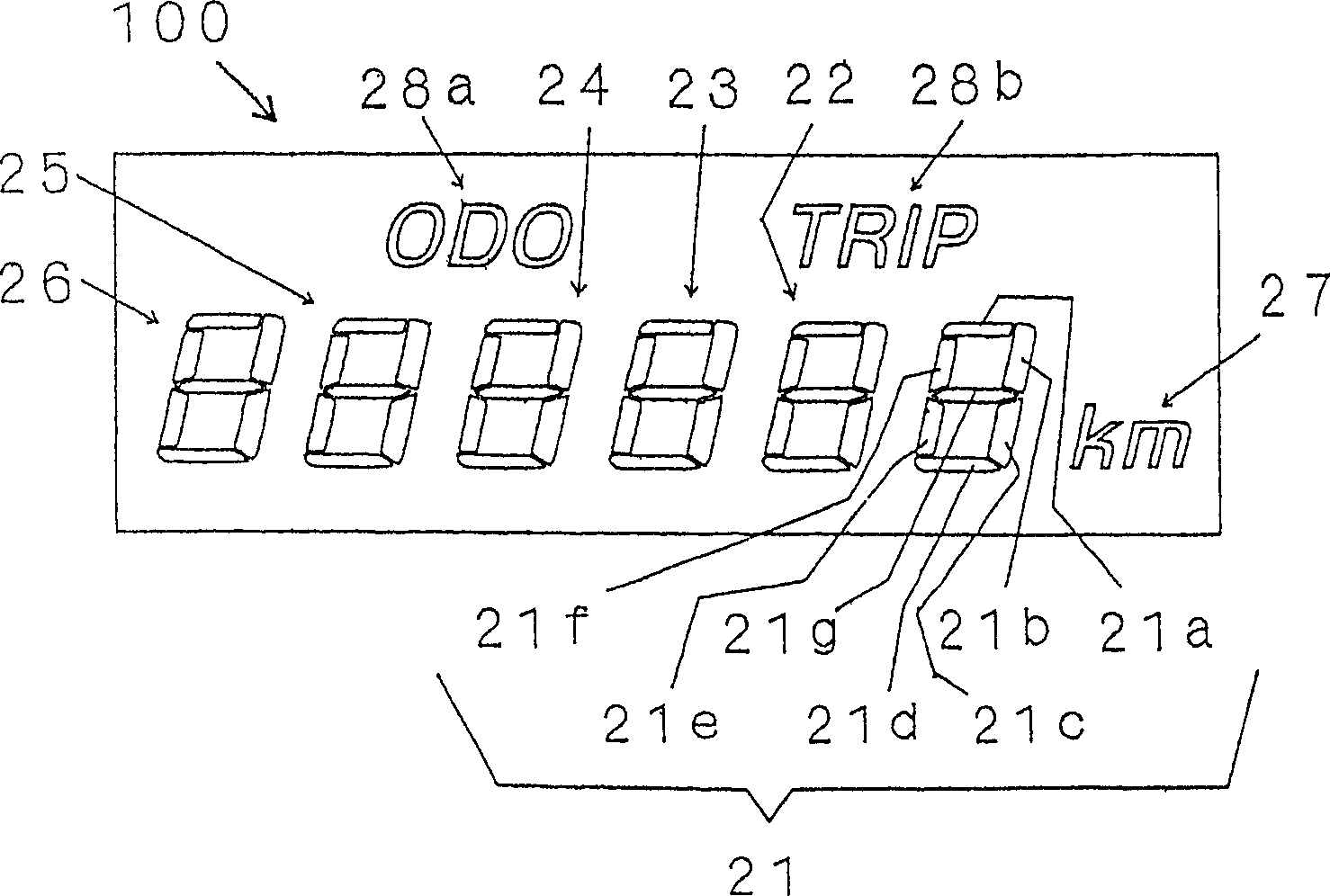
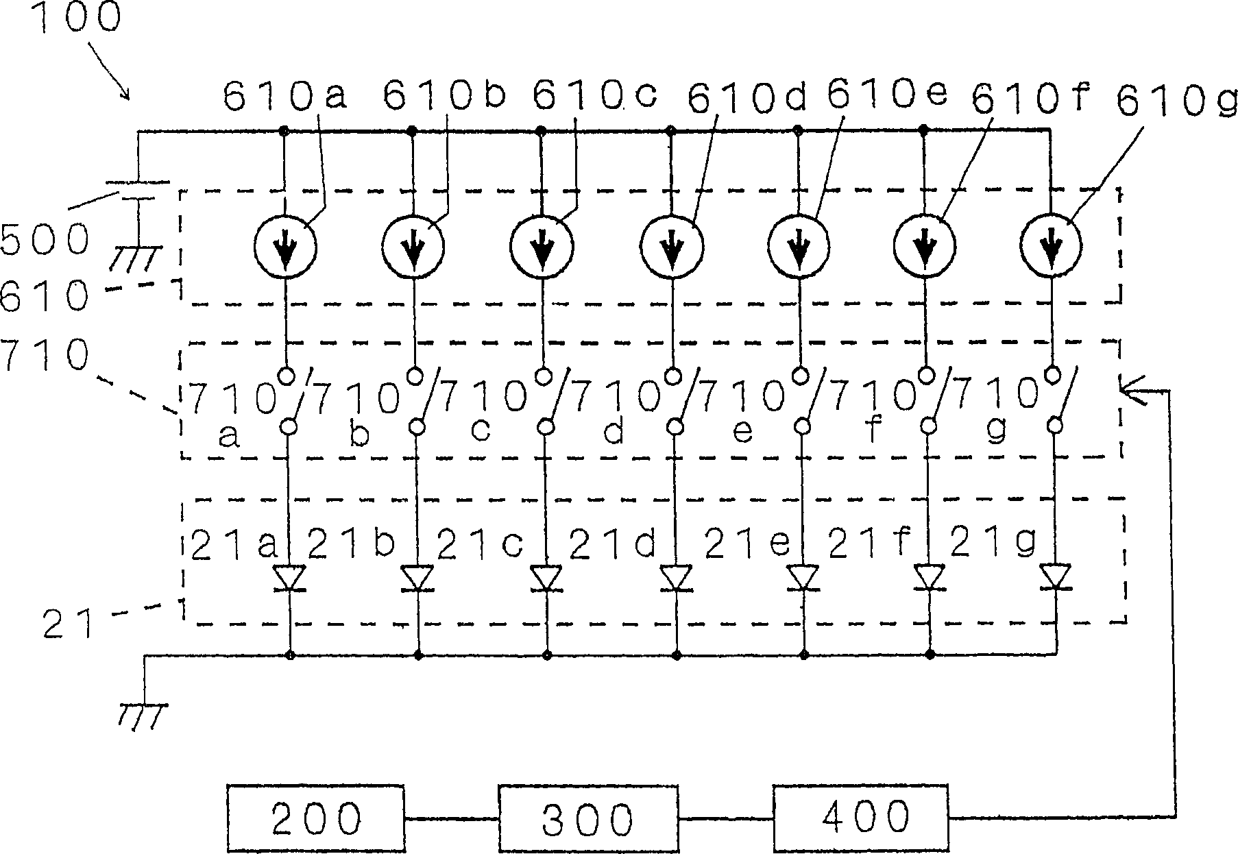
[0027] Figure 1~3 Referring to the first embodiment of the present invention, reference numeral 100 represents a light-emitting display of the present invention, which adopts OLED 5 (refer to Figure 5 ) digital travel distance meter with a display for vehicles.

[0028] Cathode 2 (see Figure 5 ) is divided into 6 groups 21-26, which are formed in the following manner. The method is: the group 21 is divided into 7 segments 21a-21g forming the light-emitting parts arranged in the shape of a "day", which are represented in an analog way Arabic numerals "0" to "9" and other groups 22 to 26 are the same, and by arranging a plurality of groups 21 to 26 horizontally, 6 digits can be displayed. In addition, group 21 is l...


PUM


Abstract

A luminous display unit (100) which uses self-luminescent elements lowered in luminance according to a luminous time and has a plurality of segments (21a-21g) (luminous locations) with different luminous times at these luminous locations. During the use time of the luminous display unit (100), a luminous location providing a long luminous time and that providing a short luminous time originally have different luminances so that the difference in luminance between the both luminous locations is not identified during the use time.

Description

technical field [0001] The present invention relates to reducing the difference between different light-emitting parts in light-emitting displays (for example, light-emitting displays using organic electroluminescent elements (OLEDs) or fluorescent display tubes (FLTs), or light-emitting diodes (LEDs), etc., which are inherently light-emitting elements). The method of brightness difference between. Background technique [0002] Such as Figure 5 As shown, for example, the following OLED 5 is disclosed in Japanese Invention Patent Application Publication No. 32307 / 1994. The OLED 5 includes an anode 2 formed of a transparent conductive material such as indium tin oxide (ITO) at least on a transparent substrate 1. , an organic layer formed of one or more layers (at least formed of a single-layer structure of an organic light-emitting layer, or a multi-layer structure in which an anode layer, corresponding to an organic light-emitting layer, is stacked and formed An electron ho...

Claims


Application Information

Patent Timeline
Patent Type & Authority Patents(China)
IPC IPC(8): G09G3/12G09G3/04G09G3/14H01L51/50
CPCG09G3/12G09G3/14
Inventor 若井仁资丸山淳一
Owner NIPPON SEIKI CO LTD
Why Eureka
Try Eureka