
Multi-axial electric machinery process equipment

A technology of linear motors and processing equipment, applied in the direction of metal processing equipment, metal processing machinery parts, manufacturing tools, etc., can solve the problems of bulkiness, equipment cost increase, pillar defects, etc.

Inactive Publication Date: 2006-09-06
CAMOZZI MACHINE TOOLS
View PDF1 Cites 5 Cited by
  • Summary
  • Abstract
  • Description
  • Claims
  • Application Information

AI Technical Summary

Problems solved by technology

[0006] The defect of the processing equipment involved in the patent document US5,368425 is that only a very heavy and bulky structure can be used to meet the above working conditions, and also, for its dynamic structural parts or processing equipment parts that may move during processing, especially The pillars that make up the Y axis of the device are all flawed
In fact, this defect is reflected in the increase of equipment cost and the increase of overall weight

Method used


Image

  • Multi-axial electric machinery process equipment
  • Multi-axial electric machinery process equipment
  • Multi-axial electric machinery process equipment

Examples


Embodiment Construction

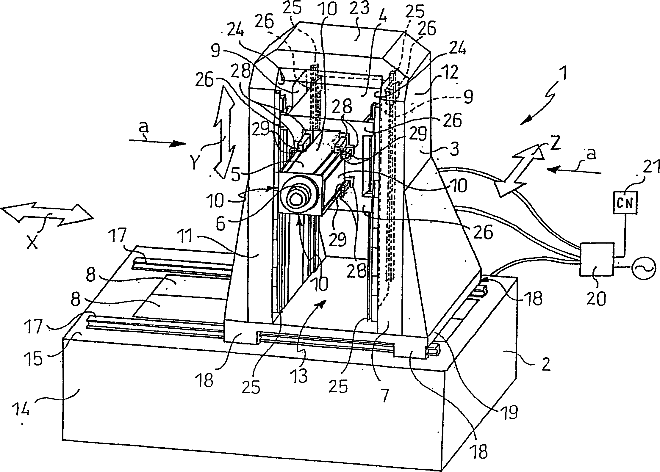
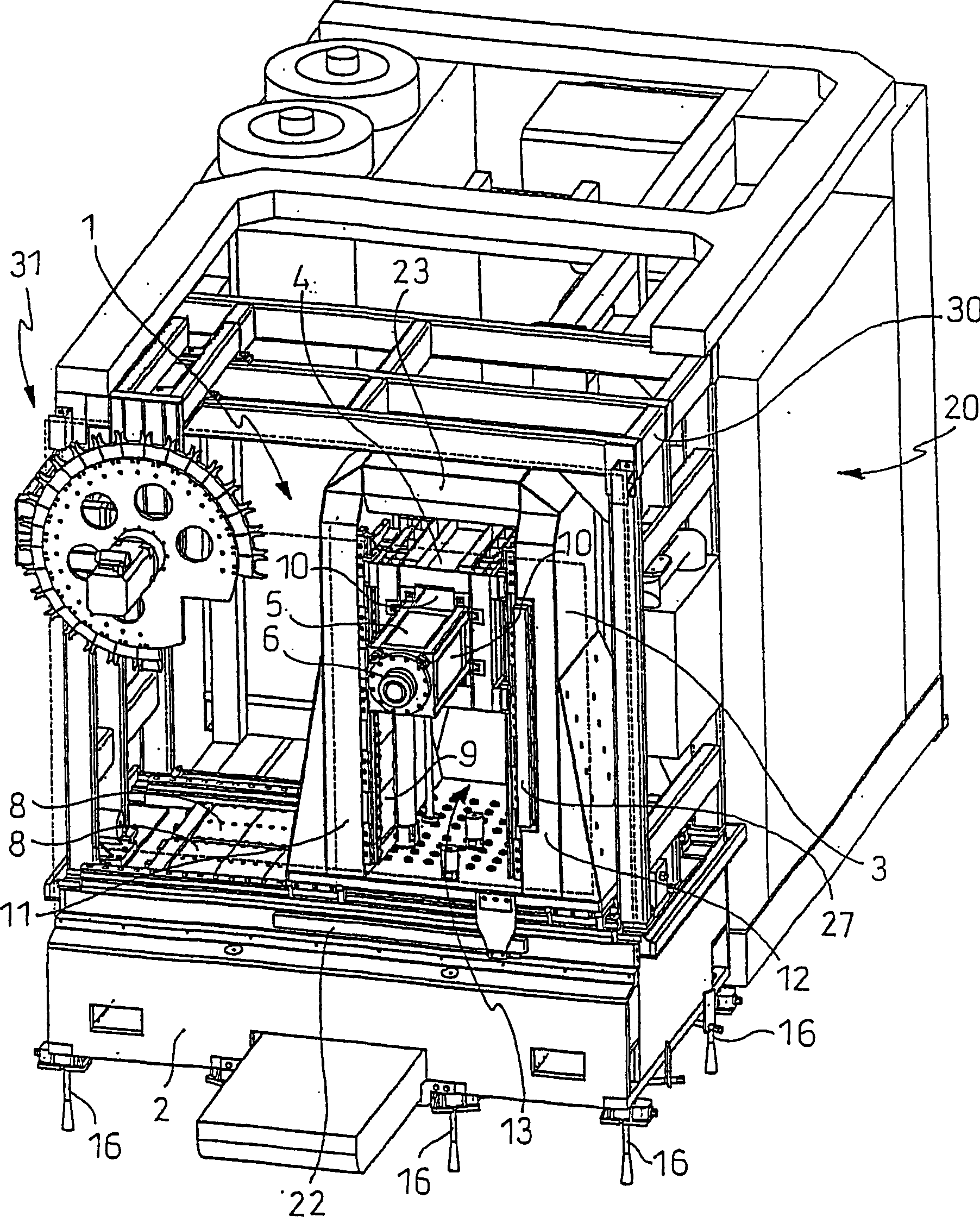
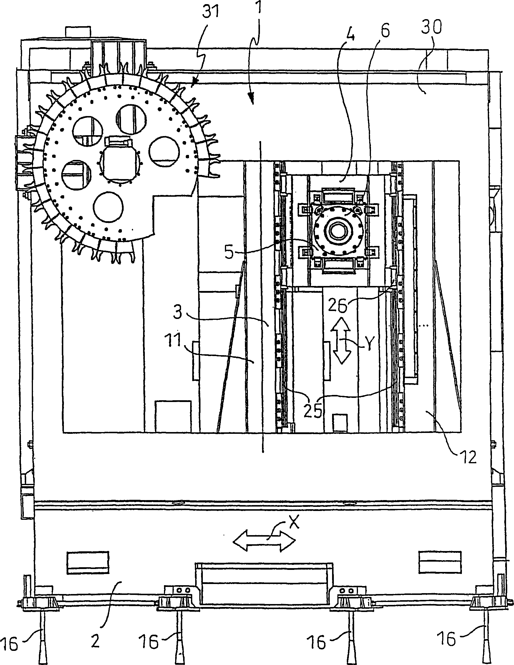
[0017] Referring to the above-mentioned drawings, the processing equipment is generally indicated as 1 . The processing device 1 comprises a bed 2 supporting at least one column 3 on which at least one saddle 4 is slidable. In said saddle mount 4 there is a main sliding mount 5 adapted to support a mandrel 6 for moving the equipment.

[0018] The bed 2 forms at least one first axis (X) arranged longitudinally along the bed 2 . For example, the above-mentioned first axis (X) may be arranged horizontally. Said at least one strut 3 is operatively connected to said first axis (X) so that the bed supports it with only one of its ends 7 and guides it along said first axis (X). At least one strut 3 protrudes from the bed 2 forming a second axis (Y). For example, the second axis (Y) is arranged at right angles to the first axis (X), specifically vertically. At least one saddle 4 is supported on at least one strut 3 so that it can be guided along said second axis (Y). The bend of ...


PUM


Abstract

A machine tool (1) driven by linear motors (8, 9, 10) along a plurality of axes (X, Y, Z) and unusually robust and rigid, comprises a bed (2) which defines at least a first axis (X), at least one column (3) operably connected and supported only at one of its ends (7) by said bed (2), for its guided movement along the first axis (X), said at least one column (3) extending away from the bed (2) to define a second axis (Y), at least one saddle mount (4), for its guided movement along a third axis (Z) and supporting a spindle (6) for the movement of a tool, wherein said at least one column (3) comprises a portal structure having a first shoulder (11) opposed to a second shoulder (12) such as to define a window (13) within which the saddle mount (4) is arranged, and wherein, between said opposed shoulders (11, 12) and the saddle mount (4), linear motors (9) are interposed such as to move the saddle mount (4) along said second axis (Y), producing an effect of attraction of the shoulders (11, 12) towards the saddle mount (4).

Description

technical field [0001] The invention relates to a multi-axis linear motor processing equipment. [0002] More specifically, the subject of the invention relates to a machining device with three axes, where the device can be, for example, a chip removal tool such as a milling cutter, moved at high speed along a feed channel by means of a linear motor . Background technique [0003] Realization of this type of processing requires the fulfillment of the following conditions, that is, while moving the device continuously and rapidly, even at a strong acceleration of 0.5G, the precision of the processing can be guaranteed at the same time. This requires the design of a structure that is stiff enough not to deform during machining, yet rigid enough not to start vibrating due to the influence of motor operation or due to the mechanical stresses generated during machining. [0004] Generally, these processing devices include a column extending in the vertical direction (Y axis) wh...

Claims


Application Information

Patent Timeline
Patent Type & Authority Patents(China)
IPC IPC(8): B23Q1/01B23Q1/62B23Q5/28
CPCY10T409/304312B23Q1/626Y10T483/1736Y10T409/309744Y10T409/309576B23Q5/28B23Q1/015Y10T483/179
Inventor 阿蒂略·卡莫齐埃托雷·卡莫齐
Owner CAMOZZI MACHINE TOOLS
Learn More