
Device and method for controllable feeding gas to metallurgical vessel

A gas supply device and gas technology, applied in the manufacture of converters, burners, lighting and heating equipment, etc., to achieve cost saving, easy wear, and inhibit nozzle damage

Inactive Publication Date: 2006-09-06
VOEST ALPINE AG
View PDF0 Cites 0 Cited by
  • Summary
  • Abstract
  • Description
  • Claims
  • Application Information

AI Technical Summary

Problems solved by technology

Early atomization does not solve this problem, because the water always flows to the inner wall of the nozzle channel and forms a water film there

Method used


Image

  • Device and method for controllable feeding gas to metallurgical vessel
  • Device and method for controllable feeding gas to metallurgical vessel
  • Device and method for controllable feeding gas to metallurgical vessel

Examples


Embodiment Construction

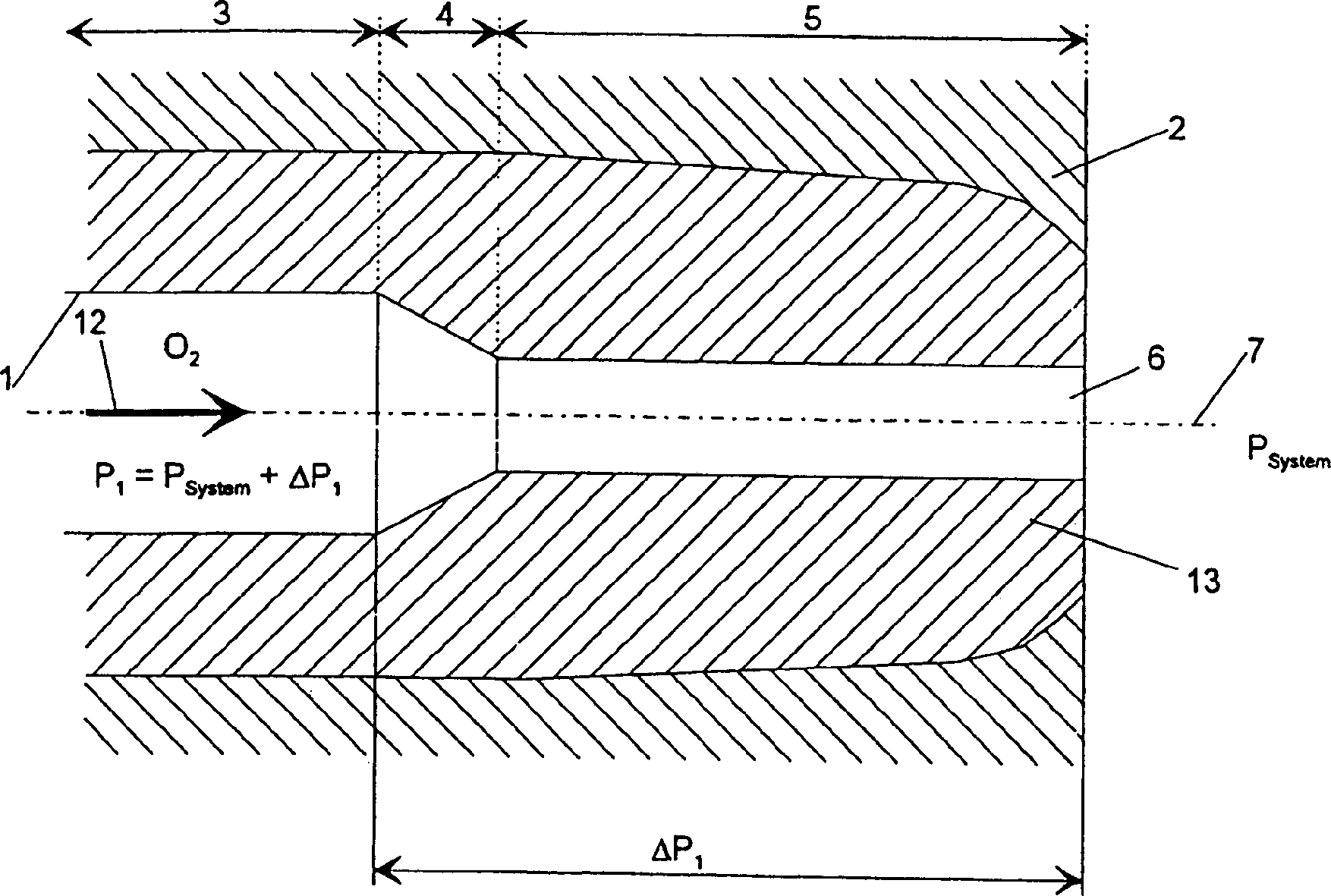
[0036] exist figure 1 , the nozzle 1 passes through the shell 2 of a metallurgical vessel such as a smelting gasifier. The nozzle 1 is formed by a water-cooled nozzle body 13 . A nozzle channel 6 runs through the nozzle body 13 , which is formed from a plurality of parts 3 , 4 and 5 and is approximately rotationally symmetrical with respect to the central longitudinal axis 7 of the nozzle channel 6 .

[0037] In this case, the inflow 3 has a substantially constant cross section, which decreases continuously in the gas flow direction 12 in the subsequent narrowing 4 . Before the gas flows into the smelting gasifier, the flow cross-section remains essentially unchanged at the outflow 5 .

[0038] At the inlet 3 there is an inlet pressure P 1 , which reduces the pressure difference ΔP over the remaining length of the nozzle channel 6 1 down to system internal pressure P system .

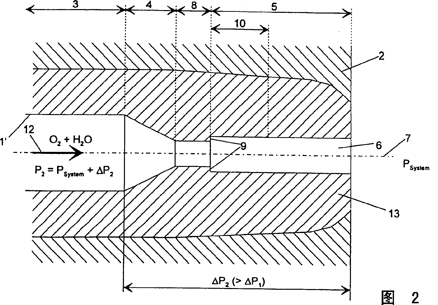
[0039] The nozzle 1' shown in FIG. 2 also has an outflow 3 with a substantially constant flow...


PUM


Abstract

The invention relates to a method for feeding a gas to a metallurgical vessel, the gas carrying a component in the gaseous and / or liquid state that can be condensed or evaporated. The gas is fed to the metallurgical vessel via one or more gas feeding devices. The gas speed is continuously increased in a first section in a number of gas feeding devices, and the gas is intimately mixed in a vortex zone with the components that can be condensed or evaporated. The gas speed is substantially maintained constant in a discharge section and the gas that is intimately mixed with the component carried along is blown into the metallurgical vessel. The invention also relates to a gas feeding device for carrying out the inventive method. The inventive method and the inventive gas feeding device allow prevention and / or reduction of nozzle damages.

Description

technical field [0001] The invention relates to a method for feeding gas into a metallurgical container, carrying gaseous and / or liquid components that can condense and / or evaporate, and feeding the gas into a metallurgical vessel through one or more gas supply devices and a gas supply device for implementing the method container. Background technique [0002] Oxygen-containing gases such as air or oxygen-enriched air or industrial oxygen are fed through gas nozzles into the metallurgical vessel and in particular the metallurgical gasifier. In order to control the process and influence the process, condensable or vaporizable components must be blown into metallurgical vessels together with the corresponding gases. These components are usually formed from water or water vapor. [0003] To thereby be able to vary the flame temperature at the oxygen nozzle, water vapor is fed into the smelting gasifier. Since water vapor is not always available, there is the other possibilit...

Claims


Application Information

Patent Timeline
Patent Type & Authority Patents(China)
IPC IPC(8): C21C5/46C21C5/48C21B7/16C21B13/00F27D3/16F27B3/22F23D11/38C21B5/00
CPCF27B3/225C21B5/00C21B7/16C21B13/00C21C5/4606F27D3/16C21C5/46C21C5/34
Inventor K·维德尔J·沃姆M·T·埃尔-拉耶斯
Owner VOEST ALPINE AG
Learn More