Plastic spool cutter

A pipe cutting machine, plastic wire technology, applied in metal processing, etc., can solve the problems of high energy consumption, uneven cutting section, high noise, etc., to achieve the effect of reducing cutting chips, reducing motor drive, and smooth cutting section

Inactive Publication Date: 2006-09-20
冯德富
View PDF0 Cites 0 Cited by
  • Summary
  • Abstract
  • Description
  • Claims
  • Application Information

AI Technical Summary

Problems solved by technology

[0002] The plastic wire pipe cutting machine is mainly used to cut the plastic wire pipe drawn by the tractor, but the cutting machine commonly used in the market is a circular saw type cutting machine, and the cutting method is mainly to use the cylinder to install the motor shaft The rapidly rotating circular saw wheel moves from bottom to top to achieve the purpose of cutting plastic profiles. However, due to the large thickness of the circular saw wheel, chips often splash when cutting plastic profiles, which greatly wastes materials. In addition, the noise is large, the cutting section is uneven, and the energy consumption is large, so it is difficult to meet the customer's requirements

Method used


Image

  • Plastic spool cutter
  • Plastic spool cutter
  • Plastic spool cutter

Examples


Embodiment Construction

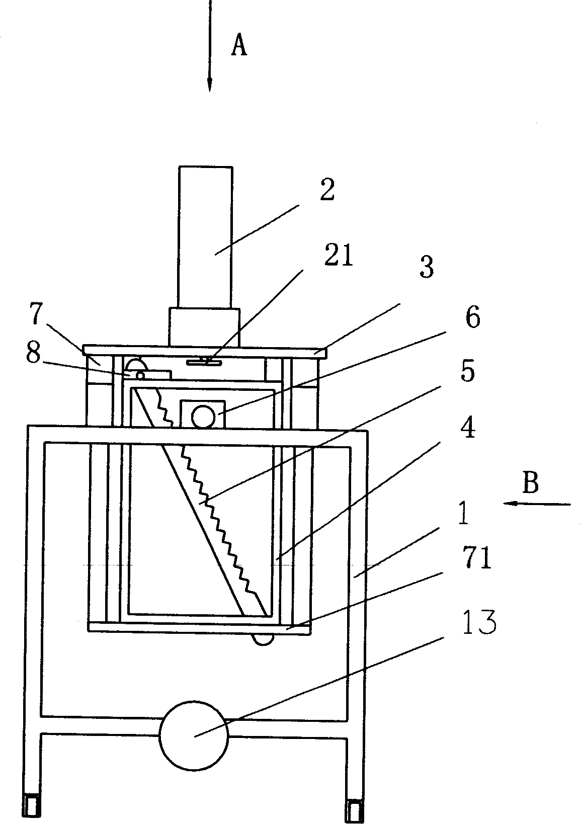
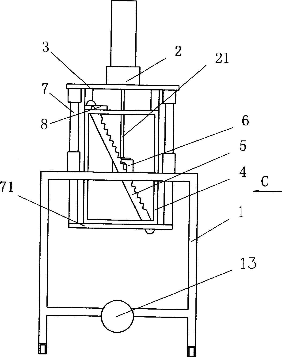
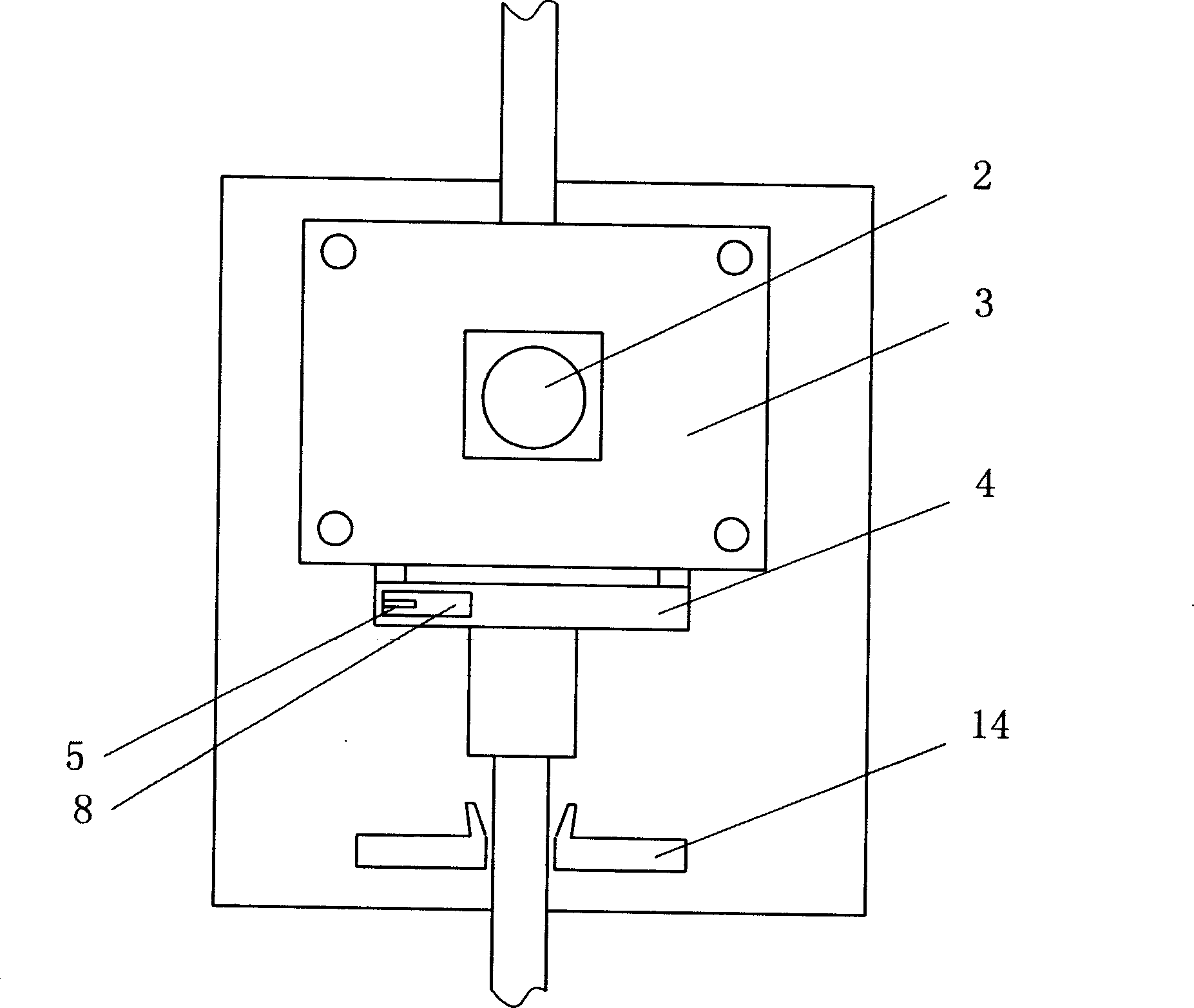
[0013] refer to figure 1 , figure 2 , image 3 , a kind of plastic wire pipe cutting machine of the present invention, it comprises frame 1, is installed on frame 1 and is driven by cylinder 2 elevating platform 3, below elevating platform 3 is fixedly connected with vertical knife rest 4, vertical knife rest 4 A cutting blade 5 is fixedly installed obliquely on the upper side, and a wire tube positioning and pressing block 6 is installed below the lifting platform 3. The movement track of the cutting blade 5 passes through the outlet of the wire tube positioning pressing block 6, and the lifting platform Four end angles of 3 are respectively equipped with telescopic positioning rod 7, and telescopic positioning rod 7 not only supports lifting platform 3 above the frame 1, but also makes lifting platform 3 more stable when rising or falling.

[0014] The working principle of the present invention is: the plastic wire tube enters the positioning and pressing block 6 on the f...


PUM


Abstract

A cutting machine for plastic bobbin is composed of machine frame, lifting platform installed on machine frame and driven by cylinder, vertical tool carrier fixed to said platform, cutting blade fixed to said tool carrier, and the bobbin pressing block under said platform.

Description

technical field [0001] The invention relates to the field of plastic wire pipe extrusion machinery, in particular to a plastic wire pipe cutting machine. Background technique [0002] The plastic wire pipe cutting machine is mainly used to cut the plastic wire pipe drawn by the tractor, but the cutting machine commonly used in the market is a circular saw type cutting machine, and the cutting method is mainly to use the cylinder to install the motor shaft The rapidly rotating circular saw wheel moves from bottom to top to achieve the purpose of cutting plastic profiles. However, due to the large thickness of the circular saw wheel, chips often splash when cutting plastic profiles, which greatly wastes materials. Moreover, the noise is large, the cutting section is uneven, and the energy consumption is relatively large, so it is difficult to meet the requirements of customers. Contents of the invention [0003] In order to overcome the deficiencies of the prior art, the in...

Claims


Application Information

Patent Timeline
Patent Type & Authority Patents(China)
IPC IPC(8): B26D1/06B26D5/08B26D7/02B29C47/08
Inventor 龙国才
Owner 冯德富
Why Eureka
Try Eureka