Driver current control apparatus and methods

a current control and drive motor technology, applied in the field of electronic circuits, can solve problems such as airbag deployment and squib firing, and achieve the effect of reducing the drive to the pass element and preventing excessive steady-state current flow

Active Publication Date: 2015-11-05
TEXAS INSTR INC
View PDF1 Cites 5 Cited by
  • Summary
  • Abstract
  • Description
  • Claims
  • Application Information

AI Technical Summary

Benefits of technology

[0014]Apparatus and methods disclosed herein implement steady-state and fast transient electronic current limiting through power transistors, including power transistors used as pass elements associated with general purpose drivers. Embodiments herein prevent excessive steady-state current flow through one or more driver pass elements and / or through load elements in series with the pass element(s) via current balancing through a current regulating preamplifier.
[0015]Such embodiments also employ a sense element with an input coupled to the pass element input and a drain-to-source equalizer circuit to help ensure accurate current sensing and current balancing between the sense element and the pass element in a 1:N ratio. The current sense element and the preamplifier contribute to a current regulation loop with negative feedback. The feedback loop regulates current through the pass element to a steady-state over-current limitation value when high currents might otherwise flow through the pass element. A current path including a current channel associated with the sense element causes the current regulating preamplifier output voltage to decrease in the case of a steady-state over-current condition, thus reducing drive to the pass element. Steady-state over-current protection is available when the driver circuitry is powered on.

Problems solved by technology

Without transient voltage spike protection, simply connecting the car battery might cause squib firing and air bag deployment.

Method used


Image

  • Driver current control apparatus and methods
  • Driver current control apparatus and methods
  • Driver current control apparatus and methods

Examples


Embodiment Construction

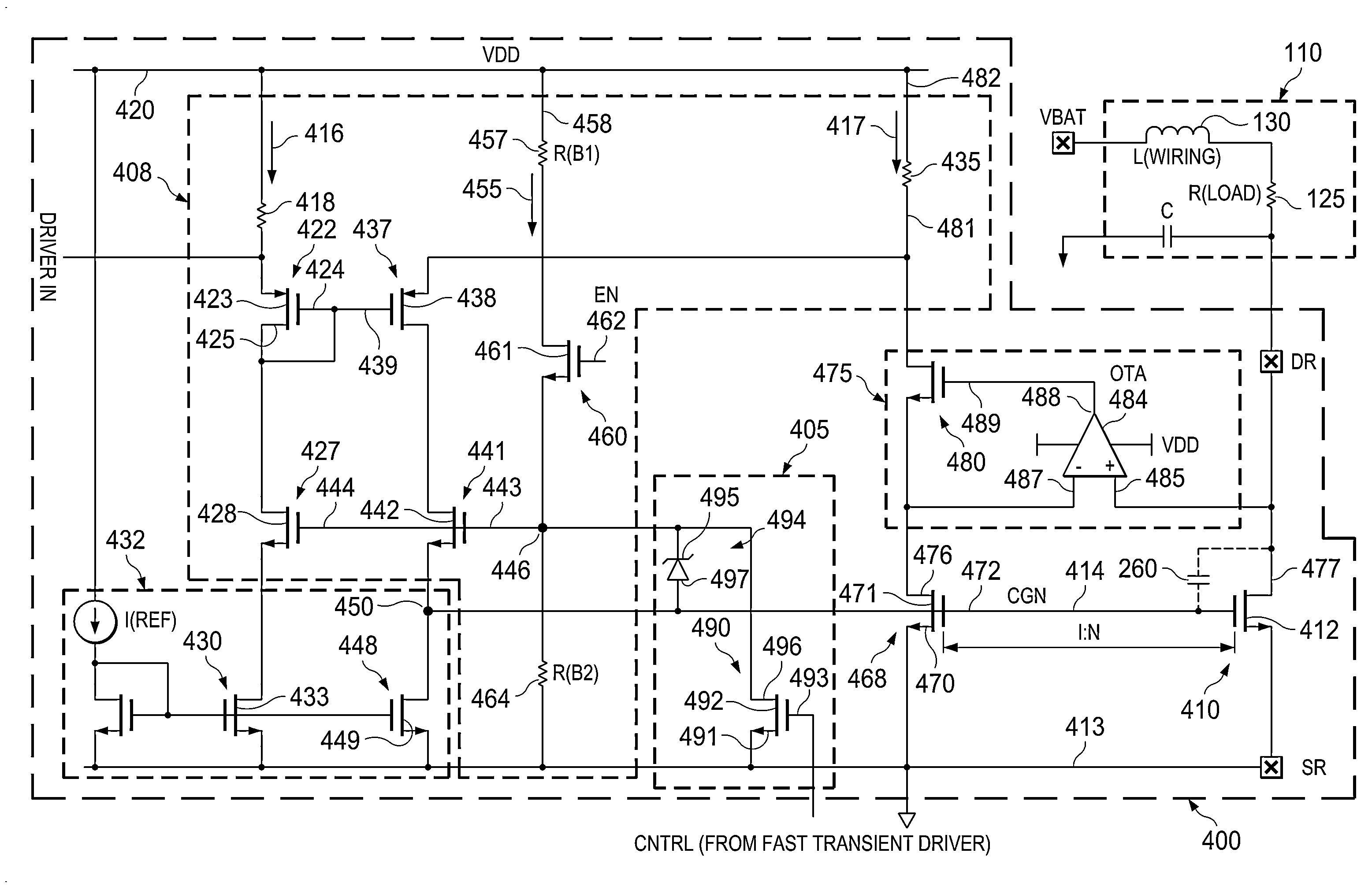
[0017]FIG. 4 is a schematic diagram of a general purpose driver and electronic current-limiting apparatus 400 according to various example embodiments of the invention. The driver and current-limiting apparatus 400 includes a steady-state over-current protection circuit and a fast transient switch 405 associated with a transient over-current protection circuit. A transient over-current control circuit portion of the transient over-current protection circuit is described below in conjunction with a detailed description of FIG. 5. FIG. 4 additionally illustrates an example driver load circuit 110 as previously described.

[0018]The driver and electronic current-limiting apparatus 400 includes a current regulating preamplifier 408. The current regulating preamplifier 408 establishes a desired level of current through current-bearing components of the load circuit 110, including load resistance 125 and inductance 130. The current-bearing components 125 and 130 of the load 110 will be refe...


PUM


Abstract

Apparatus and methods disclosed herein implement steady-state and fast transient electronic current limiting through power transistors, including power transistors used as pass elements associated with general purpose drivers. Embodiments herein prevent excessive steady-state current flow through one or more driver pass elements and / or through load elements in series with the pass element(s) via a current sensing and driver preamplifier feedback loop. A transient over-current protection circuit includes a fast transient switch and a transient over-current control circuit. The transient over-current control circuit rectifies one or more transient voltage spikes to create a momentary direct current (DC) voltage power supply (MVS) to power a fast transient driver circuit and to trip the fast transient switch. The fast transient switch discharges a transient pass element input voltage (e.g., a gate voltage on a MOSFET power transistor in some embodiments) and terminates current flow through the pass element current channel.

Description

TECHNICAL FIELD[0001]Structures described herein relate to electronic circuits, including current-limiting circuits associated with power transistors and general purpose drivers.BACKGROUND INFORMATION[0002]FIGS. 1 and 2 are prior-art schematic diagrams of general purpose drivers 100 and 200 and example load circuits 110. General purpose configurable drivers provide regulated currents for applications such as light-emitting diodes (LEDs), “squibs” (small explosive devices) used in automobile air bag deployment systems, etc.[0003]FIG. 1 illustrates a “high side” configuration, so-called because the load circuit 110 is switched to the high side (e.g., to the drain 112 in this particular example) of the pass element 115. The pass element 115 is typically driven by a preamplifier (e.g., the preamplifier 120) and passes current to the load circuit 110. In an example automobile application, R(LOAD) 125 may represent one or more LEDs, an airbag squib, etc. as previously mentioned. L(WIRING)...

Claims


Application Information

Patent Timeline
Patent Type & Authority Applications(United States)
IPC IPC(8): H02H9/02H02H9/00
CPCH02H9/005H02H9/025G01F1/667G01F1/662
Inventor EASWARAN, SRI NAVANEETHAKRISHNAN
Owner TEXAS INSTR INC
Why Eureka
Try Eureka