Floor entvance device for elevator

A technology of entrances and exits, floors, applied in the direction of elevators, transportation and packaging in buildings

Inactive Publication Date: 2006-10-04
MITSUBISHI ELECTRIC CORP
View PDF1 Cites 0 Cited by
  • Summary
  • Abstract
  • Description
  • Claims
  • Application Information

AI Technical Summary

Problems solved by technology

[0005] In order to solve the above traditional problems, the purpose of the present invention is to provide a floor entrance and exit device for elevators. One of the purposes is to effectively control the warping of the panel by alleviating the restraint of the panel by the reinforcement member or the liner when the panel undergoes thermal expansion during a fire. To prevent the fire gate from falling off and improve the fire performance

Method used


Image

  • Floor entvance device for elevator
  • Floor entvance device for elevator
  • Floor entvance device for elevator

Examples


Embodiment Construction

[0018] Embodiments of the present invention will be described below in conjunction with the accompanying drawings. In each figure, the same or corresponding parts are denoted by the same symbols, and the description thereof may be simplified or omitted.

[0019] Embodiment 1

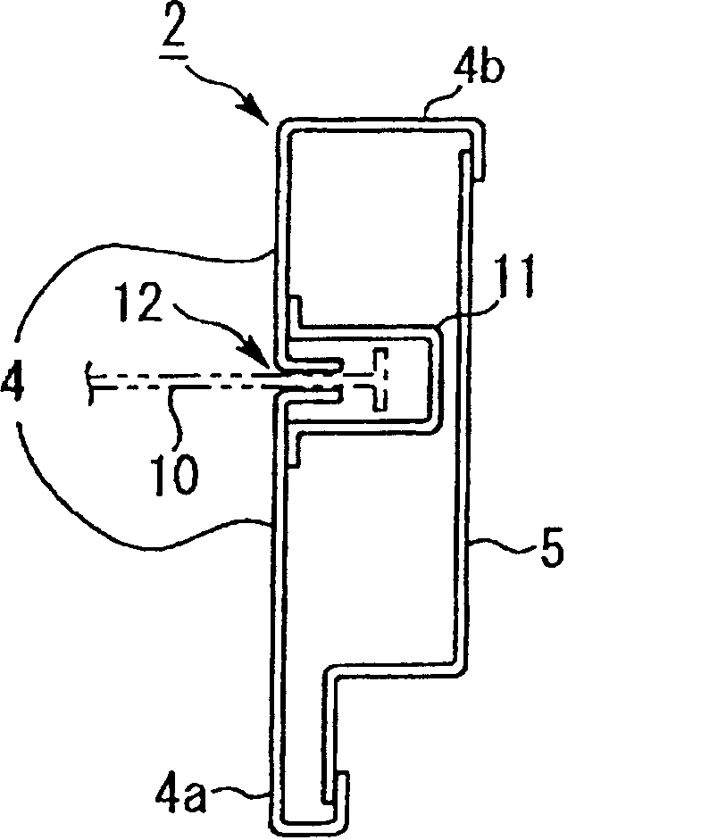
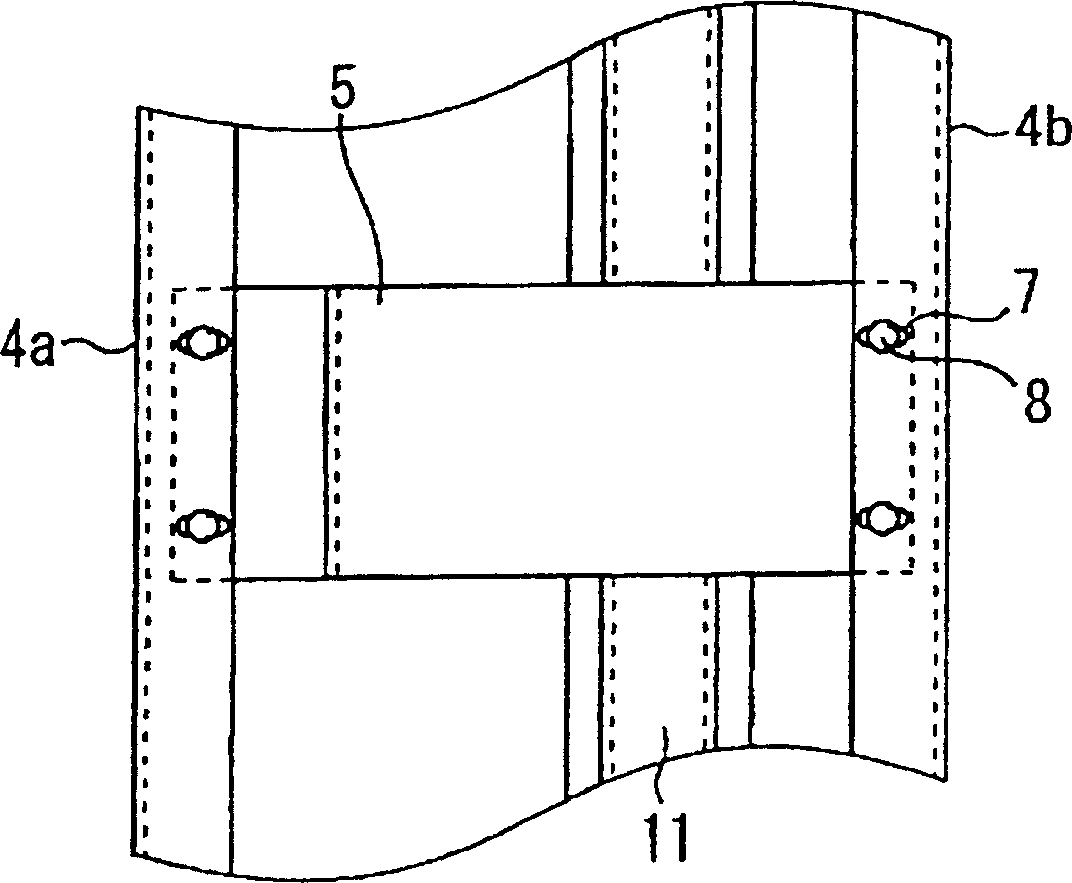
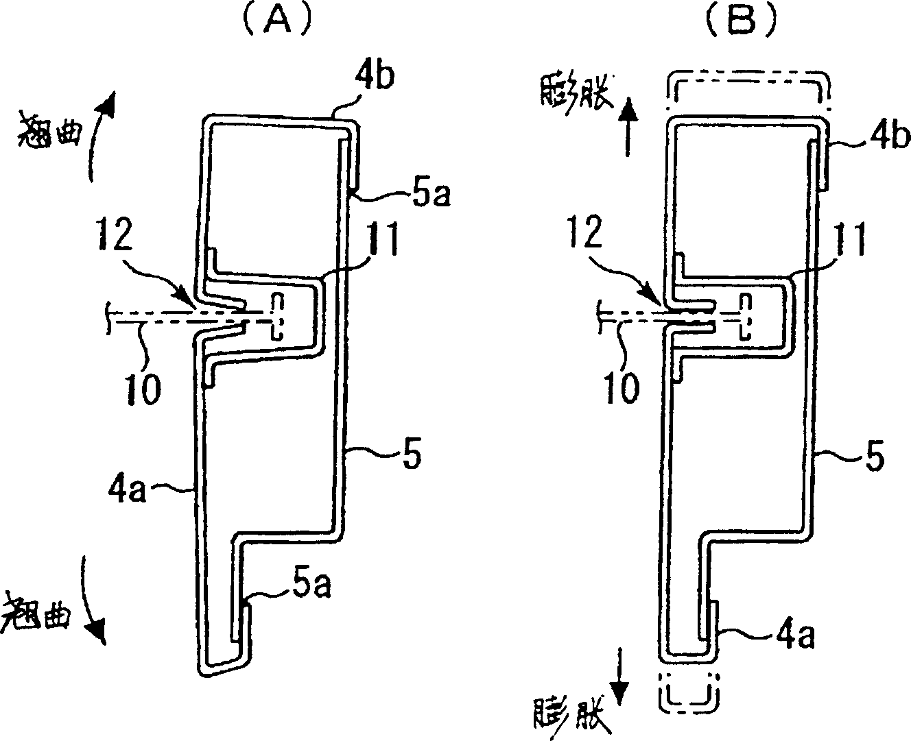
[0020] figure 1 It is a horizontal sectional view of the three-sided frame mullion of the floor entrance of the present invention. The floor entrance and exit device of the elevator seen from the floor entrance and exit side of the elevator and Figure 7 same as shown, so quoting Figure 7 . exist Figure 7 Among them, 1 is the floor entrance and exit door of the elevator, 2 is the three-sided frame mullion arranged opposite to the left and right, and 3 is the upper frame of the three-sided frame. exist figure 1 Among them, 2 is a three-sided frame mullion represented by a section in the horizontal direction, 4 is a panel, 4a is an entrance and exit side panel, and 4b is a side panel of an elevator...


PUM


Abstract

This elevator landing entrance device comprises a surface plate 4 constituting a decorated face of a vertical frame 2 of a jamb; a reinforcing member 5 enabling the surface plate 4 to slide at a joint part in a horizontal direction at the time of thermal expansion of the surface plate 4; and a fire protecting shutter 10 guided by a rail groove 12 and lowered by an upper frame 3 of the jamb. As another constitution of this invention, the reinforcing member 5 is composed of a material having a linear expansion coefficient larger than the surface plate 4, or ends are rotatably jointed to both ends of the surface plate 4 at stepped positions against a horizontal direction, bridging both ends of the surface plate 4. The rear plate 6 is separated from the surface plate 4 and jointed with the reinforcing member 5.

Description

technical field [0001] The invention relates to a floor entrance and exit device of an elevator, in particular to a three-sided frame of the elevator. Background technique [0002] Figure 7 It is a schematic configuration diagram showing the floor entrance and exit device of an elevator viewed from the floor entrance and exit side of a general elevator. exist Figure 7 Among them, 1 is the floor entrance and exit door of the elevator, 2 is the three-sided frame mullion arranged opposite to the left and right, and 3 is the upper frame of the three-sided frame. Figure 8 yes Figure 7 The horizontal section view of the three-sided frame mullion of . exist Figure 8 Among them, 4 is a panel, and 5 is a reinforcing member. The face plate 4 and each end of the reinforcement member 5 are fixed by welding, and 5a is the welded fixing part. [0003] In the event of a fire, fire gates are sometimes installed on three-sided frames for the purpose of improving fire performance. ...

Claims


Application Information

Patent Timeline
Patent Type & Authority Patents(China)
IPC IPC(8): B66B13/30
Inventor 山田真明野村健二铃木稔也西村信宽花岛真人
Owner MITSUBISHI ELECTRIC CORP
Why Eureka
Try Eureka