

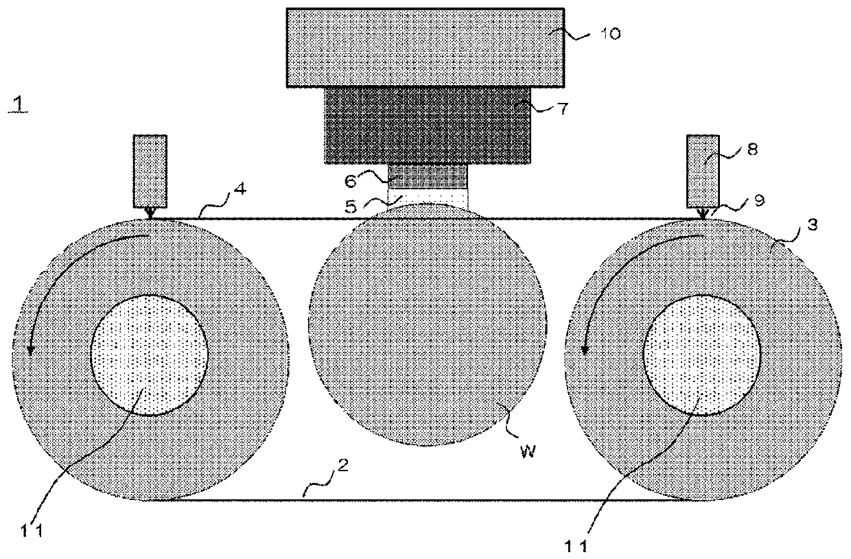
Wire saw device and wafer manufacturing method
A technology of wire saws and wafers, which is applied in manufacturing tools, fine working devices, semiconductor/solid-state device manufacturing, etc., and can solve problems such as workpiece warping
- Summary
- Abstract
- Description
- Claims
- Application Information
AI Technical Summary
Problems solved by technology
Method used
Image

Examples
Embodiment Construction
[0030] As described above, in the past, a method of controlling the warpage of the wire movement direction of the cut workpiece in the wire saw device has not been determined.
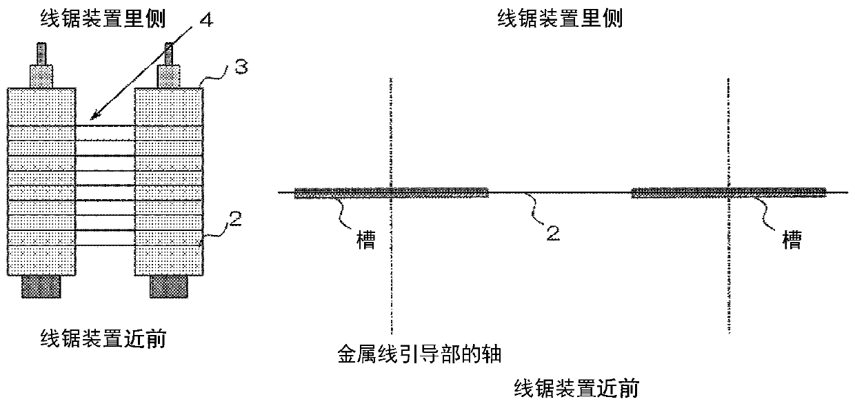
[0031] The inventors of the present invention have repeatedly actively studied the above-mentioned problems and found that by adjusting the parallelism of the axis of the wire guide portion, the wire can be bent in the front-rear direction of the wire saw device during workpiece cutting. In addition, it was found that the warpage in the moving direction of the wire of the workpiece after cutting can be controlled by this, and the present invention was completed.
[0032] Hereinafter, the wire saw device and the wafer manufacturing method of the present invention will be described in detail with reference to the drawings, but the present invention is not limited thereto. In addition, in the present invention, "parallelism (parallelism adjustment amount)" refers to the amount of inclination of the axis in the...
PUM
 Abstract
Description
Claims
Application Information