Supercharge Your Innovation With Domain-Expert AI Agents!

Detector for moving object

A technology for moving objects and detection devices, which is applied in the directions of measurement devices, antenna supports/installation devices, measurement of electrical variables, etc. The effect of reducing, simplifying the circuit structure, and increasing the degree of freedom

Inactive Publication Date: 2006-10-25
FUJITSU GENERAL LTD +1
View PDF0 Cites 0 Cited by
  • Summary
  • Abstract
  • Description
  • Claims
  • Application Information

AI Technical Summary

Problems solved by technology

[0018] In the moving object detection device of the above-mentioned prior art, Image 6 The circuit of the one-element type shown is simple, but the problem is that the amplification gain of the field effect transistor is not large enough to obtain satisfactory reception sensitivity
[0019] on the other hand, Figure 7 The problem with the two-element type moving object detection device shown is that the cost increases due to the complexity of the circuit and the large number of elements
[0020] In the single-element type and two-element type moving object detection devices, since all circuit elements are housed in the cavity resonator, it is necessary to connect an antenna to the opening when changing the moving object detection area, so the problem is, not only Increased cost and increased detector size

Method used


Image

  • Detector for moving object
  • Detector for moving object
  • Detector for moving object

Examples


Embodiment Construction

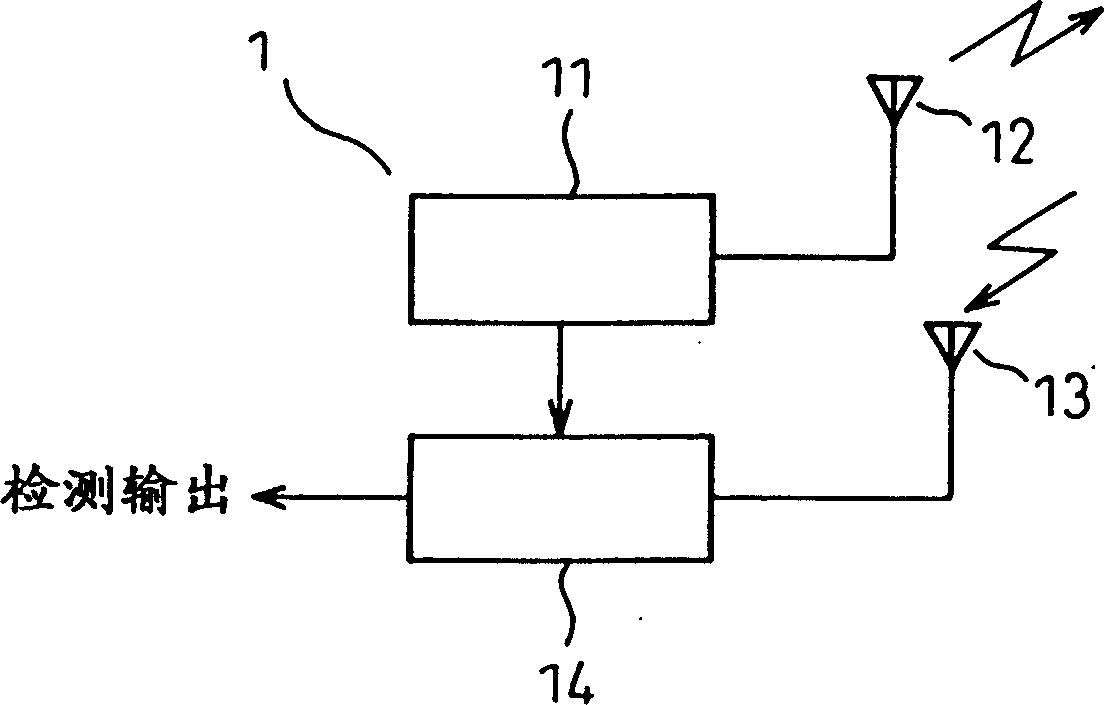
[0039] Figure 9 Main parts of the moving object detection device according to the present invention are shown. A field effect transistor 11, such as a gallium arsenide field effect transistor or a heterojunction field effect transistor, is used as an oscillator in a cavity resonator 16, and the gate region of the field effect transistor 11 is connected to an Transmit-receive antenna 19 external to cavity resonator 16 . One of the source and the drain of the field effect transistor is connected to a power supply, and the other is grounded. The output of the field effect transistor 11 is coupled to the transmitting-receiving antenna 19 through the resonant line 20 and radiated outward; with the same transmitting-receiving antenna 19, the reflected wave is received, and a node P connected between the antenna 19 and the field effect transistor 11 Obtain the moving object detection signal, that is, the detection output.

[0040]Generally, the gate region (gate) of a field effec...


PUM


Abstract

A moving object detection device, wherein an oscillating output from a grid area of ​​a field effect transistor used as an oscillator is coupled to a transmitting-receiving antenna via a resonant line, and a signal transmitted from the antenna is received at the grid area. And as a wave returning as a reflected wave, a one-beat signal component output from the grid area caused by a phase difference between the transmitted wave and the reflected wave is taken as a moving object detection signal.

Description

technical field [0001] The invention relates to a moving object detecting device for detecting whether a moving object, especially an object such as a person, a vehicle, an obstacle, a fixed object (hereinafter collectively referred to as "object") is moving. Background technique [0002] figure 1 A block diagram of a moving object detection device 1 is shown. The output of an oscillating circuit 11 is radiated from a transmitting antenna 12 to an object, and a wave reflected from the object is received by a receiving antenna 13; the reflected wave is then mixed with a portion of the transmitted wave in a receiving circuit 14 to generate a beat signal . The beat signal as a detection output is sent to a detection circuit, and the detection circuit outputs a moving object detection signal. [0003] If the object is in motion, the frequency of the reflected wave shifts due to the Doppler effect. When the frequency of the emitted wave is, for example, f 0 , the reflection ...

Claims


Application Information

Patent Timeline
Patent Type & Authority Patents(China)
IPC IPC(8): G01S13/50H01Q13/08G01R27/02G01R27/04G01S7/03G01S13/00G01S13/36H01Q1/22H01Q1/38
CPCG01S7/35G01S13/56
Inventor 土桥长一郎佐佐木義弘白鸟英喜
Owner FUJITSU GENERAL LTD
Features
  • R&D
  • Intellectual Property
  • Life Sciences
  • Materials
  • Tech Scout
  • Unparalleled Data Quality
  • Higher Quality Content
  • 60% Fewer Hallucinations
Learn More