Single shaft double eccentric negative offset rolling shearing machine

A double-eccentric, negative-offset technology, applied in shearing devices, shearing machines, metal processing equipment, etc., to achieve the effect of consistent quality, straight end faces of steel plates, and extended service life

Inactive Publication Date: 2006-11-08
TAIYUAN UNIVERSITY OF SCIENCE AND TECHNOLOGY
View PDF0 Cites 0 Cited by
  • Summary
  • Abstract
  • Description
  • Claims
  • Application Information

AI Technical Summary

Problems solved by technology

[0003] Aiming at the technical problems existing in the existing single-axis double-eccentric rolling shears, the present invention provides a single-axis double-eccentric negative-bias rolling shear that improves the shearing conditions of the arc shear blades.

Method used


Image

  • Single shaft double eccentric negative offset rolling shearing machine
  • Single shaft double eccentric negative offset rolling shearing machine
  • Single shaft double eccentric negative offset rolling shearing machine

Examples


Embodiment Construction

[0051] The embodiment will be further described according to the accompanying drawings. This embodiment is used to illustrate the present invention, but not to limit the present invention.

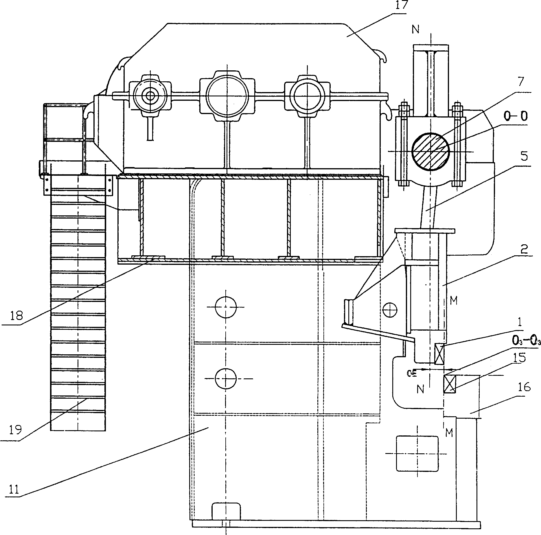
[0052] In this embodiment, a large-scale rolling shear machine designed by a steel company is taken as an example, and the machine is set as a single-axis double-eccentric negative bias structure. The shear force is 850KN, and the shear steel plate size is 40×2700×6000~120000. 15 cuts per minute.

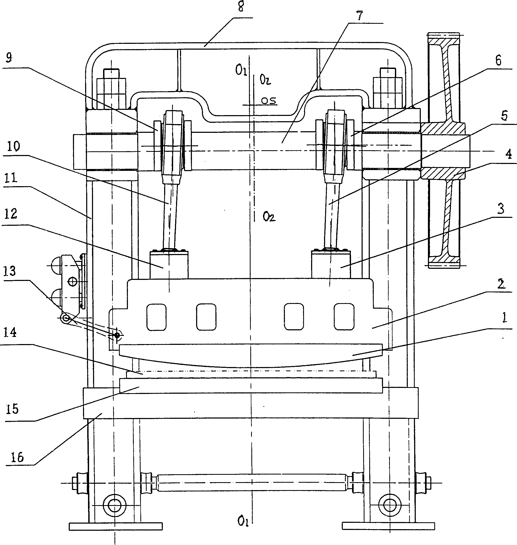
[0053] Single-axis double-eccentric negative-bias rolling shearing machine is composed of frame 11, arc upper shear blade 1, lower shear blade 15, crank linkage mechanism, etc., arc upper scissors 1 are installed on upper tool holder 2, right hinged 3 and the left hinge 12 are installed on the upper tool rest 2, the upper end of the left connecting rod 10 is connected with the left crank 9, the lower end is connected with the left hinge 12, the upper end of the right connecting rod 5 is connect...


PUM


Abstract

The invention belongs to the technical field of steel rolling auxiliary equipment, and in particular relates to an improvement of the installation position of the crankshaft in a rolling steel plate shearing machine. The rod mechanism is characterized by the horizontal offset distance (OE) of the crankshaft rotation center line (O-O) relative to the vertical plane (M-M) where the shear line is located to the fuselage. (OE) is calculated according to the following formula: OE= L 2 sinβ-esinθ 2 , The offset distance (OE) is 44mm-100mm. A negative bias is generated, and at the moment of the maximum shearing force during the shearing process, under the same shearing moment, the force exerted by the crank on the connecting rod can be increased, and at the same time, the horizontal component force of the force can be increased Increase, so that there is a greater force to press the upper knife frame to the frame, to ensure that the cutting edge clearance is constant. The force between the crank and the connecting rod is more balanced and reasonable; the end face of the sheared steel plate is straight without warping or edge collapse, which greatly improves the shearing quality of the steel plate.

Description

technical field [0001] The invention belongs to the technical field of steel rolling auxiliary equipment, and in particular relates to an improvement of the installation position of a crankshaft in a rolling steel plate shearing machine. Background technique [0002] In the prior art, the rolling steel plate shearing machine adopts a single-axis double eccentric transmission mode, and the crankshaft rotation center line O-O of the single-axis double eccentric steel plate shearing machine and the shearing line O formed by the upper and lower cutting blades 3 -O 3 Parallel, the vertical planes N-N and M-M where they are located coincide, that is, they are in the same vertical plane, and the crankshaft centerline and shear line are parallel and in the same vertical plane. This structure produces an overturning force deviating from the frame body when the steel plate is cut, which affects the cutting quality to a certain extent and greatly reduces the life of the cutting edge. ...

Claims


Application Information

Patent Timeline
Patent Type & Authority Patents(China)
IPC IPC(8): B23D15/08B23D15/04
Inventor 黄庆学李玉贵孙斌煜孟进礼王晓慧
Owner TAIYUAN UNIVERSITY OF SCIENCE AND TECHNOLOGY
Why Eureka
Try Eureka