Digital mirror device projector and method of controlling amount of light being used in digital mirror device projector

A technology of reflective elements and projectors, which is applied in the direction of electrical elements, optical elements, image reproducers using projection devices, etc., and can solve problems such as inability to project images with constant brightness

Inactive Publication Date: 2006-11-08
NEC DISPLAY SOLUTIONS LTD
View PDF2 Cites 0 Cited by
  • Summary
  • Abstract
  • Description
  • Claims
  • Application Information

AI Technical Summary

Problems solved by technology

Projectors using traditional DMDs do not take this into account, and there is a problem ...

Method used


Image

  • Digital mirror device projector and method of controlling amount of light being used in digital mirror device projector
  • Digital mirror device projector and method of controlling amount of light being used in digital mirror device projector
  • Digital mirror device projector and method of controlling amount of light being used in digital mirror device projector

Examples


Embodiment Construction

[0036] The best mode for carrying out the present invention will be described in more detail below using examples with reference to the accompanying drawings.

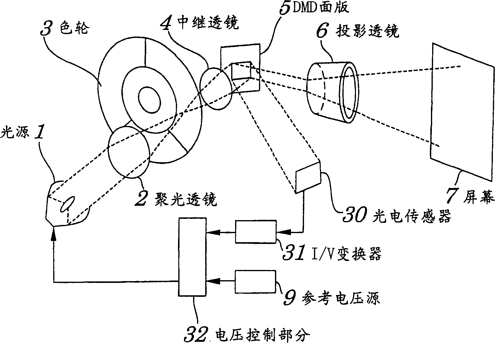
[0037] figure 1 It is an explanatory diagram of main parts of a one-chip projector using a DMD (Digital Reflective Device) panel according to an embodiment of the present invention.

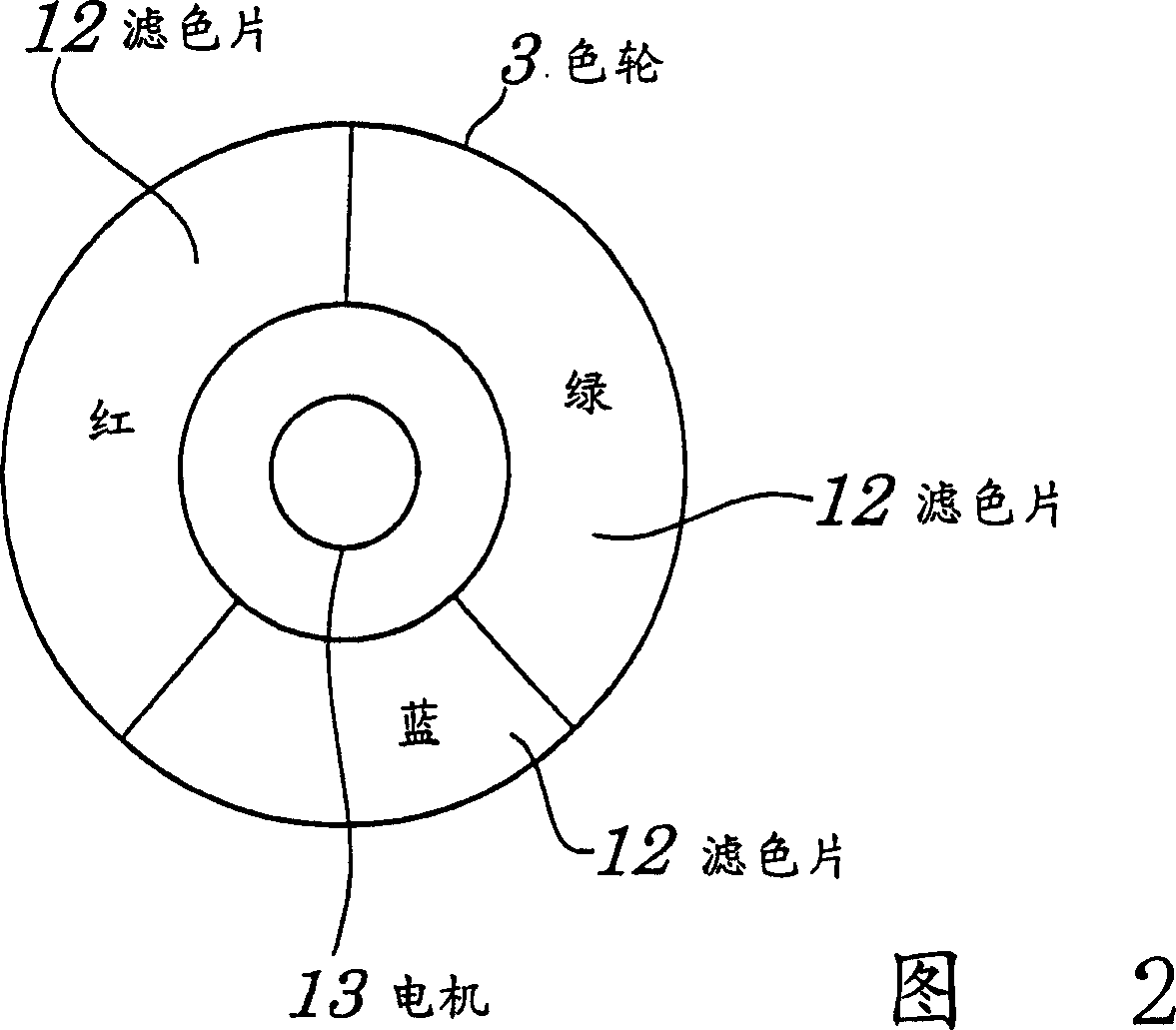
[0038] According to the projector of this embodiment, such as figure 1 As shown, it has light source 1, condenser lens 2, color wheel 3, relay lens 4, DMD panel 5, projection lens 6, screen 7, reference voltage source 9, photoelectric sensor (photoelectric conversion device) 30, I / V conversion device 31, voltage control section 32, and image controller (not shown).

[0039] In this embodiment, the operation of the DMD panel 5 having a plurality of mirror elements is controlled by an image controller (not shown) as a driving section. The image controller controls the deflection state of each mirror element constituting the DMD panel 5...


PUM


Abstract

A digital reflective element (DMD) projector comprising: a voltage controllable light source; a color wheel with color filters; a DMD panel with a plurality of mirror elements each controllable to set It is the first deflection state and the second deflection state, and when it is set to the first deflection state, it reflects the light supplied by the light source and passed through any color filter to form image light traveling along the first direction, and When it is set to the second deflection state, the light supplied by the light source and passed through any color filter is reflected, and the reflected light travels along the second direction; the image controller controls it according to the grayscale signal to make each mirror surface the units are all set to the first or second deflection state; the photosensor, which is arranged in such a position that light reflected from the mirror unit can be incident on the photosensor when the mirror unit is in the second deflection state, and thereby the photosensor receiving reflected light and converting the reflected light into a voltage; a reference voltage source generating a preset reference voltage; and a voltage controller for comparing the output voltage of the photoelectric sensor with the preset reference voltage generated by the reference voltage source, and controlling the The amount of light supplied by the light source makes this voltage equal to the preset reference voltage.

Description

technical field [0001] The present invention relates to a digital mirror device (Digital mirror device) (hereinafter may be abbreviated as "DMD") projector using a plurality of mirror units, and a method for controlling the amount of light used in the digital mirror device projector. methods, and more particularly to a DMD projector capable of efficiently utilizing reflected light with each mirror unit turned off, and a method of controlling the amount of light for such a digital reflective element projector. [0002] This application claims priority from Japanese Patent Application No. 2002-080854 filed on March 22, 2002, which is incorporated herein by reference. Background technique [0003] For example, as disclosed in Japanese Patent Application Publication No. Hei 10-78550, the commonly known DMD (Digital Reflective Device) projector uses a DMD panel with hundreds of thousands of mirror units, each of which is mounted on The deflection is therefore controllable on the...

Claims


Application Information

Patent Timeline
IPC IPC(8): G03B21/00H04N5/66G02B26/08G02B26/00G02B27/18G03B33/12H04N5/74H04N9/31
CPCG02B26/0833H04N9/3114H04N9/315G02B26/08
Inventor 富家修
Owner NEC DISPLAY SOLUTIONS LTD
Why Eureka
Try Eureka