

Vibration type tilting device
a tilting device and vibration technology, applied in the field of vibration type tilting devices, can solve the problems of reducing the mass moment of inertia of the mirror holder, affecting the quality of the picture, and creating vibration with a small for
Inactive Publication Date: 2008-07-08
SAMSUNG ELECTRO MECHANICS CO LTD
View PDF3 Cites 0 Cited by
- Summary
- Abstract
- Description
- Claims
- Application Information
AI Technical Summary
Benefits of technology
The solution provides a clearer and smoother display by reducing rising time and overshoot, improving tracking ability and reducing residual vibration, resulting in a more natural and continuous image projection.
Problems solved by technology
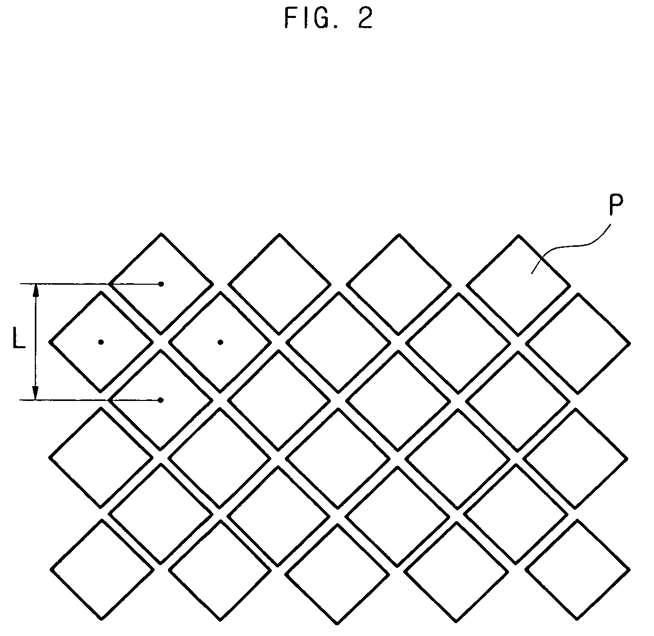
As described above, since conventional image projection devices form a large display simply through the magnified projection of the small original picture, there is the problem that the picture quality is degraded due to the grid pattern formed between each pixel P, as seen in FIG. 2.
Also, there is a problem in that when the picture moves rapidly or where the line of sight of the viewer moves rapidly, the picture is formed on the screen with rainbow colors showing where the contrast ratio is great, for example where there are black stripes on a white background, or with the grid pattern between each pixel notably significant.
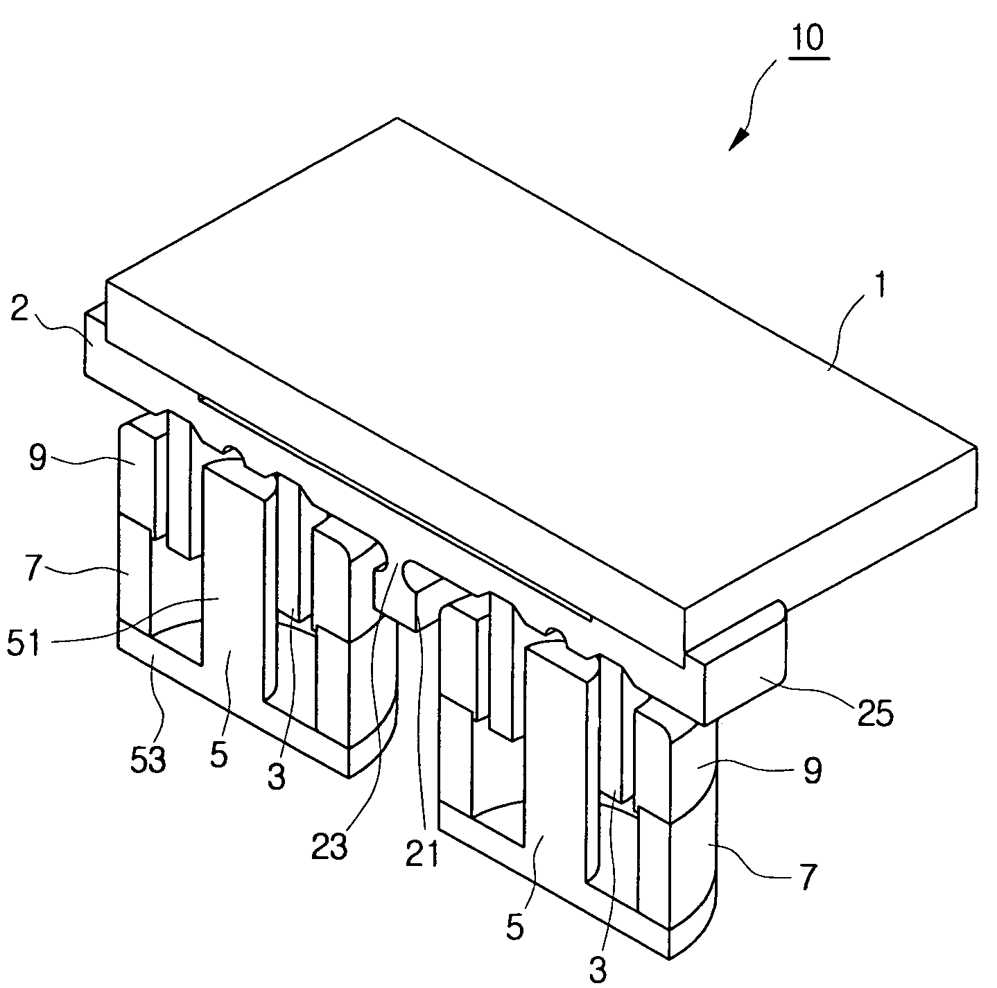
Forming the mirror holder from plastic may not only decrease the mass moment of inertia of the mirror holder and allow easy manufacture, but may also create vibration with a small force, because the Young's modulus is low compared to metal.
Method used
View moreImage
Smart ImageViewing Examples

Examples
experimental example
[0058]The mirror holder 2 had portions thereof removed, as illustrated in FIG. 4, and was formed in a cross shape, to decrease the mass moment of inertia of the mirror holder 2. Aluminum was used as the material of the mirror holder 2. The overall damping coefficient was c=0.007 (Nms), and the spring coefficient was k=38.248434 (N / m) for the mirror 1, mirror holder 2, and coil 3, with the respective mass and mass moment of inertia set as shown in Table 1 below.
[0059]
TABLE 1material, mass, and mass moment of inertia of the mirror,mirror holder, and coilmass moment ofmaterialmass (kg)inertia (kgmm2)mirrorglass0.0064730.583804mirror holderaluminum0.0020050.112866coilcopper0.0025770.188129Total0.0110550.884799
Login to View More PUM
 Abstract
A tilting device for repeatedly tilting light reflected from a micro-mirror panel is disclosed. A vibration type tilting device, comprising a mirror positioned on a light path which reflects light transmitted from a digital micro-mirror panel, a mirror holder having the mirror joined to a side thereof, a coil joined to the reverse side of the mirror holder, and a magnet which generates a magnetic field passing through the coil, where portions of the mirror holder are removed to decrease the mass moment of inertia of the mirror holder, may not only provide a smooth and natural display by periodically tilting light reflected from a digital micro-mirror panel in constant time intervals but also may improve the tracking ability of the mirror and reduce residual vibration.
Description
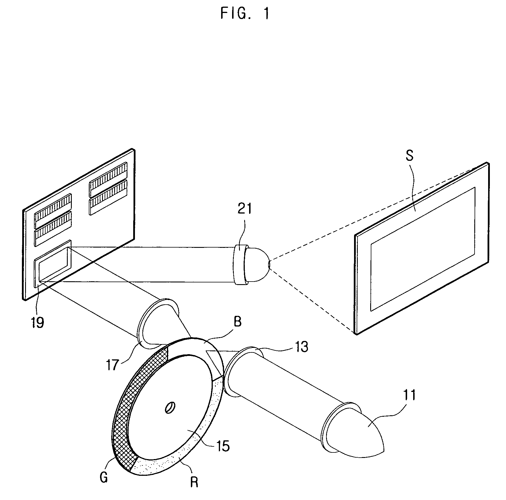
CROSS-REFERENCE TO RELATED APPLICATIONS[0001]This application claims the benefit of Korean Patent Application No. 2005-55027 filed with the Korea Industrial Property Office on Jun. 24, 2005, the disclosure of which is incorporated herein by reference.BACKGROUND[0002]1. Technical Field[0003]The present invention relates to a tilting device, and in particular, to a vibration type tilting device in which the mass moment of inertia is decreased for superior vibration performance.[0004]2. Description of the Related Art[0005]An image projection device using digital light processing (DLP), in which the mosaic phenomenon in pixels, a problem in regular liquid crystal display (LCD) imaging devices, is eliminated to improve the ability to reproduce original colors, is used widely in theaters, conference rooms, and projection TV's, etc. The image projection device can be divided into a Front Projection device and a Rear Projection device according to the projection method.[0006]The Front Proje...
Claims
Login to View More Application Information
Patent Timeline
 Patent Type & AuthorityPatents(United States)
IPC IPC(8): G02B7/182
CPCG02B26/105G02B7/1821H04N5/74
InventorMOON, YANG-HOLEE, CHIL-SUNGCHOI, DONG-WONKIM, JAE-KYUNG
OwnerSAMSUNG ELECTRO MECHANICS CO LTD