Die cushion device

a cushion device and cushion body technology, applied in the direction of forging presses, forging presses, shock absorbers, etc., can solve the problems of difficult to accurately control the press force in the rise time, and achieve the effect of slowing down the rise time, reducing the rise time of the load, and reducing the reaction for

Active Publication Date: 2011-02-24
KOMATSU LTD +1
View PDF21 Cites 20 Cited by
  • Summary
  • Abstract
  • Description
  • Claims
  • Application Information

AI Technical Summary

Benefits of technology

[0010]According to the die cushion device of the second aspect of the present invention, the speed difference peaks at the first point-of-time, i.e., a point-of-time when a predetermined period of time has elapsed after the cushion pad starts receiving the force from the slide member. The damping section thereby generates large reaction force at the first point-of-time. Consequently, the rise time of the load can be reduced in the initial phase of collision.
[0011]According to the present invention, the shock absorber device includes the elastic section and the damping section. Therefore, the elastic section can stabilize the load in the shock absorber device. Further, the damping section compensates slow rising of the load by the elastic section. Accordingly, the rise time of the load can be reduced. Yet further, when the servomotor is controlled under the condition that the speed difference between the speed of the slide member and the speed of the support section change as described above, the reaction force by the damping section also changes in accordance with the change of the speed difference. Therefore, appropriately setting the changing target value of the speed difference makes it possible to desirably adjust and shape the waveform of the press force in the rise time until the speed difference reaches the target value. Consequently, the press force in the rise time can be accurately controlled.

Problems solved by technology

In other words, it is difficult to accurately control the press force in the rise time.

Method used


Image

  • Die cushion device
  • Die cushion device
  • Die cushion device

Examples


Embodiment Construction

1. Structure

[0022]An exemplary embodiment of the present invention will be hereinafter explained with reference to figures.

1-1. Overall Structure of Press Machine 1

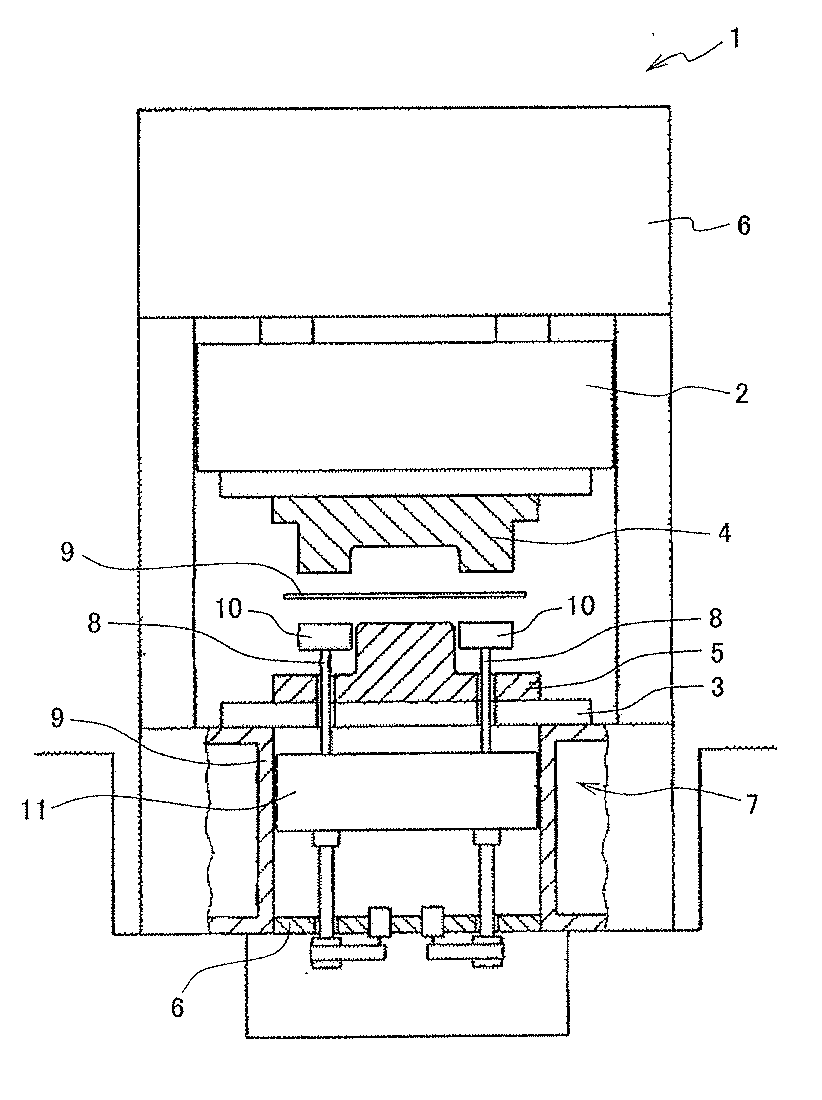
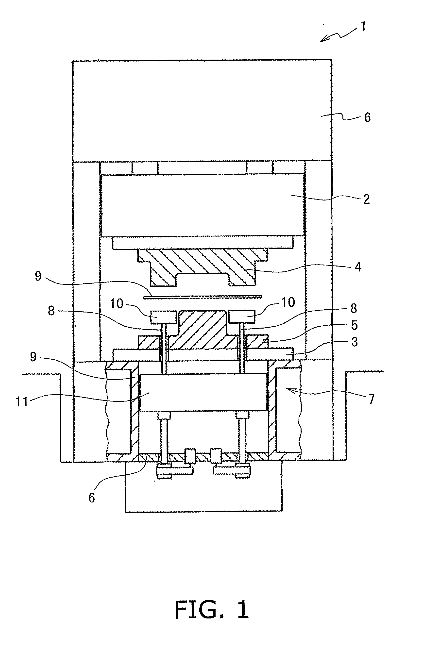
[0023]FIG. 1 is a schematic diagram illustrating the structure of a press machine 1. The press machine 1 includes a slide 2 (a slide member), a bolster 3, a pair of a top die 4 and a bottom die 5, a slide drive mechanism 6, and a die cushion device 7.

[0024]The slide 2 is disposed while being allowed to move in a vertical direction. The bolster 3 is disposed below and opposed to the slide 2. The slide drive mechanism 6 is disposed over the slide 2. The slide drive mechanism 6 is configured to raise and lower the slide 2. The top die 4 is attached to a bottom part of the slide 2. The bottom die 5 is attached to a top part of the bolster 3. Each of the bolster 3 and the bottom die 5 includes a plurality of through holes vertically penetrating therethrough. Plural cushion pins 8 described below are respectively inserted into ...


PUM

PropertyMeasurementUnit
press forceaaaaaaaaaa
forceaaaaaaaaaa
reaction forceaaaaaaaaaa

Abstract

In the die cushion device, a shock absorber device relieves shock between a cushion pad and a support section. The shock absorber device includes a damping section and an elastic section. The damping section generates reaction force in accordance with the relative speed of the cushion pad with respect to the support section. The elastic section generates reaction force in accordance with the relative displacement of the cushion pad with respect to the support section. The controller section controls a servomotor so that a speed difference between the speed of the slide member and the speed of the support section is set to be a predetermined target speed difference value that changes over time.

Description

CROSS-REFERENCE TO RELATED APPLICATIONS[0001]This national phase application claims priority to Japanese Patent Application No. 2008-134818 filed on May 22, 2008. The entire disclosure of Japanese Patent Application No. 2008-134818 is hereby incorporated herein by reference.TECHNICAL FIELD[0002]The present invention relates to a die cushion device.BACKGROUND ART[0003]The die cushion devices are installed in the press machines for applying pressure to a slide. In the die cushion devices, a cushion pad receives force from the slide moving downwards. Further, the cushion pad is configured to be moved while applying press force to the slide.[0004]In the well-known die cushion devices, a servomotor is caused to drive the cushion pad for highly accurately controlling pressure to be applied to the slide. Further, there have been produced the die cushion devices of a type configured to control the servomotor for setting a difference between the speed of the cushion pad and the speed of the ...

Claims


Application Information

Patent Timeline
Patent Type & Authority Applications(United States)
IPC IPC(8): B29C43/58
CPCB21D24/02
Inventor MIYASAKA, TAKUJISATO, HIROHIDEYOSHIMURA, RYOTANAKAGAWA, MASAYADOBA, EIJIITO, HIROYUKIARIDABE, TAKEO
Owner KOMATSU LTD
Why Eureka
Try Eureka