
Actuator for valve, in particular turbine valve

A technology of regulating mechanism and valve stem, which is applied in the direction of valve details, valve operation/release device, valve device, etc., can solve the problems of troublesome maintenance measures, high cost, poor stability, etc., and achieve the effect of reliable operation

Inactive Publication Date: 2006-12-06
SIEMENS AG
View PDF5 Cites 0 Cited by
  • Summary
  • Abstract
  • Description
  • Claims
  • Application Information

AI Technical Summary

Problems solved by technology

However, such incombustible hydraulic fluids are expensive and require rather costly maintenance measures due to their poor stability compared to mineral oil-based hydraulic fluids

Method used


Image

  • Actuator for valve, in particular turbine valve
  • Actuator for valve, in particular turbine valve
  • Actuator for valve, in particular turbine valve

Examples


Embodiment Construction

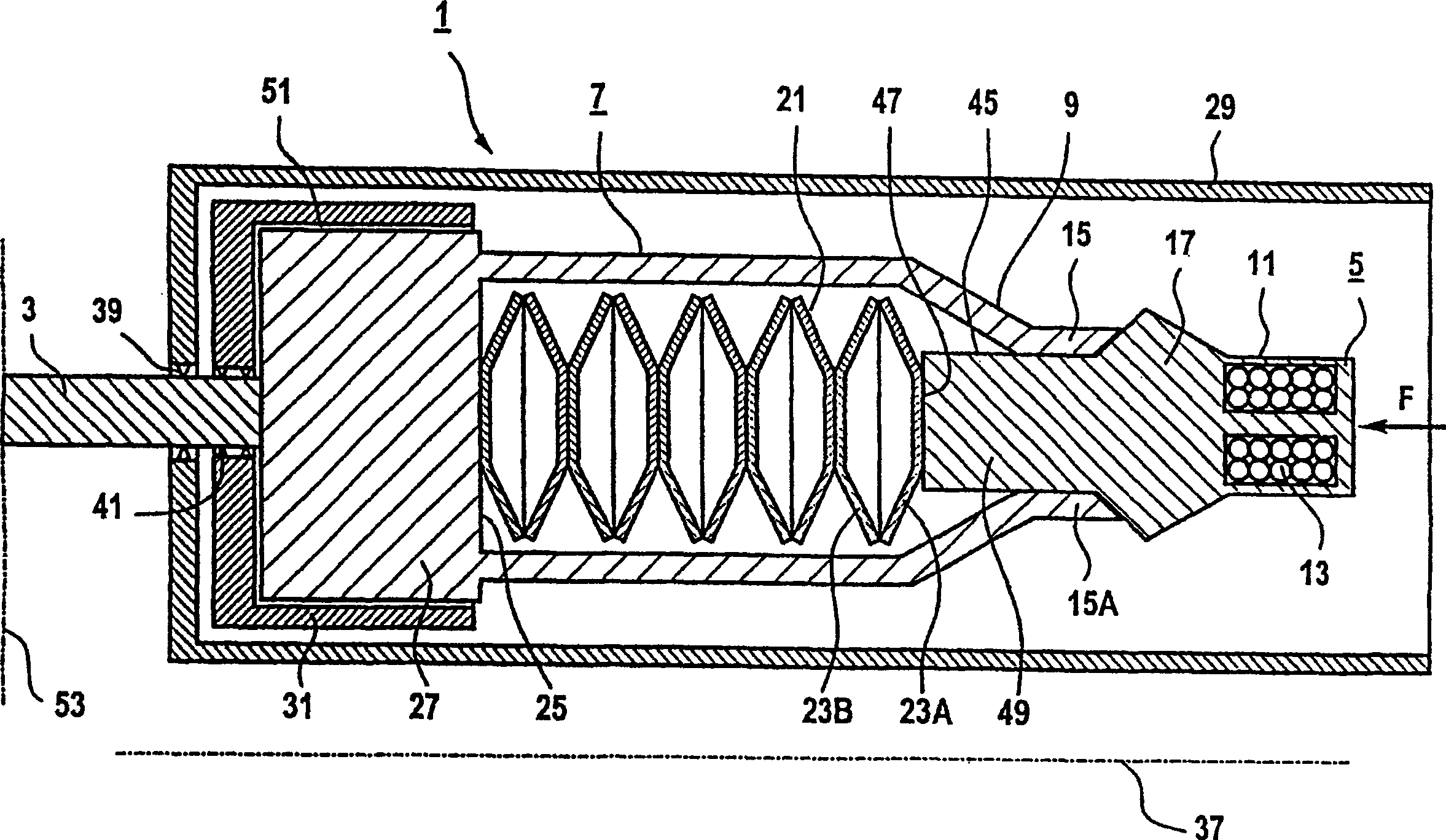
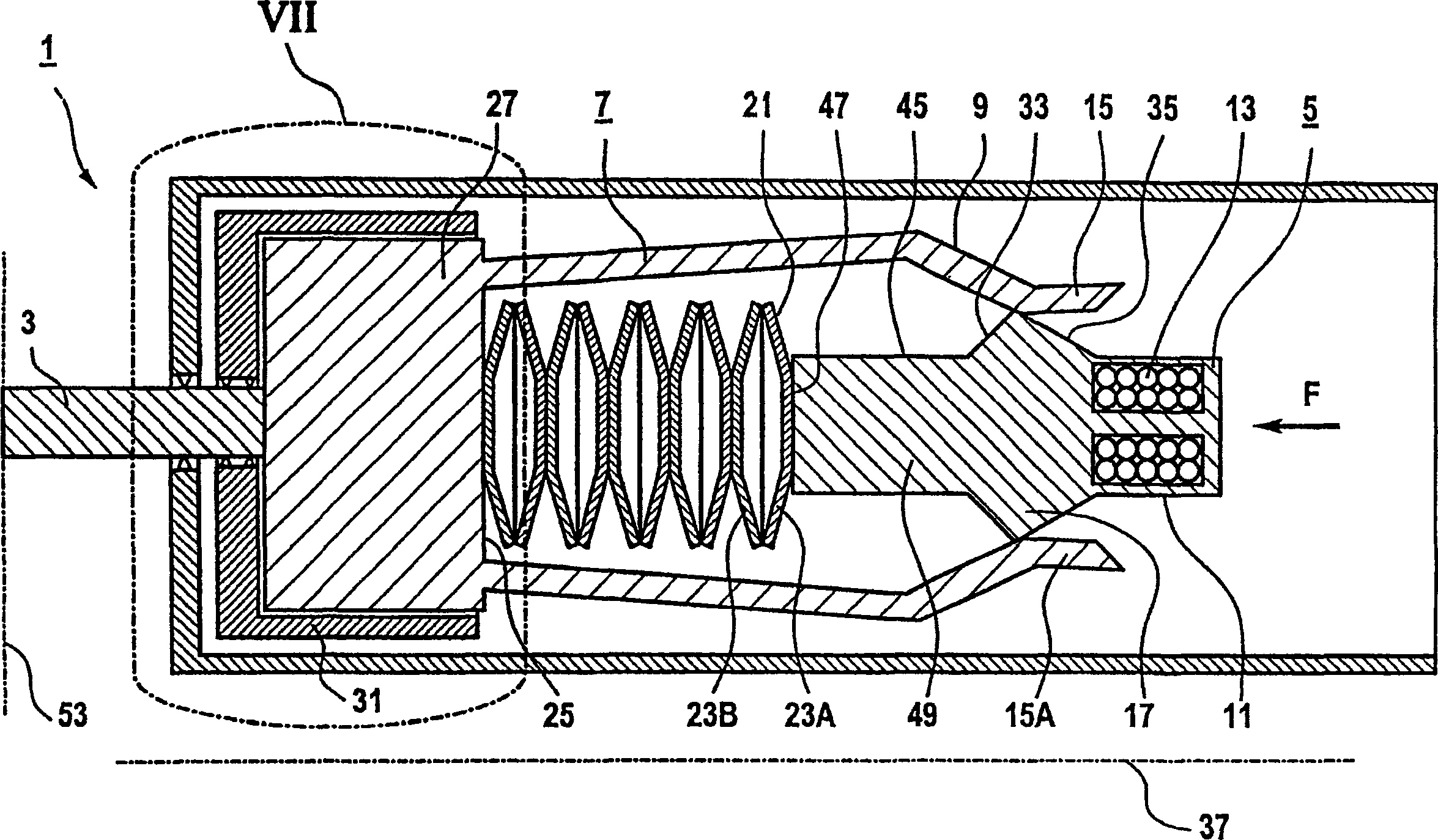
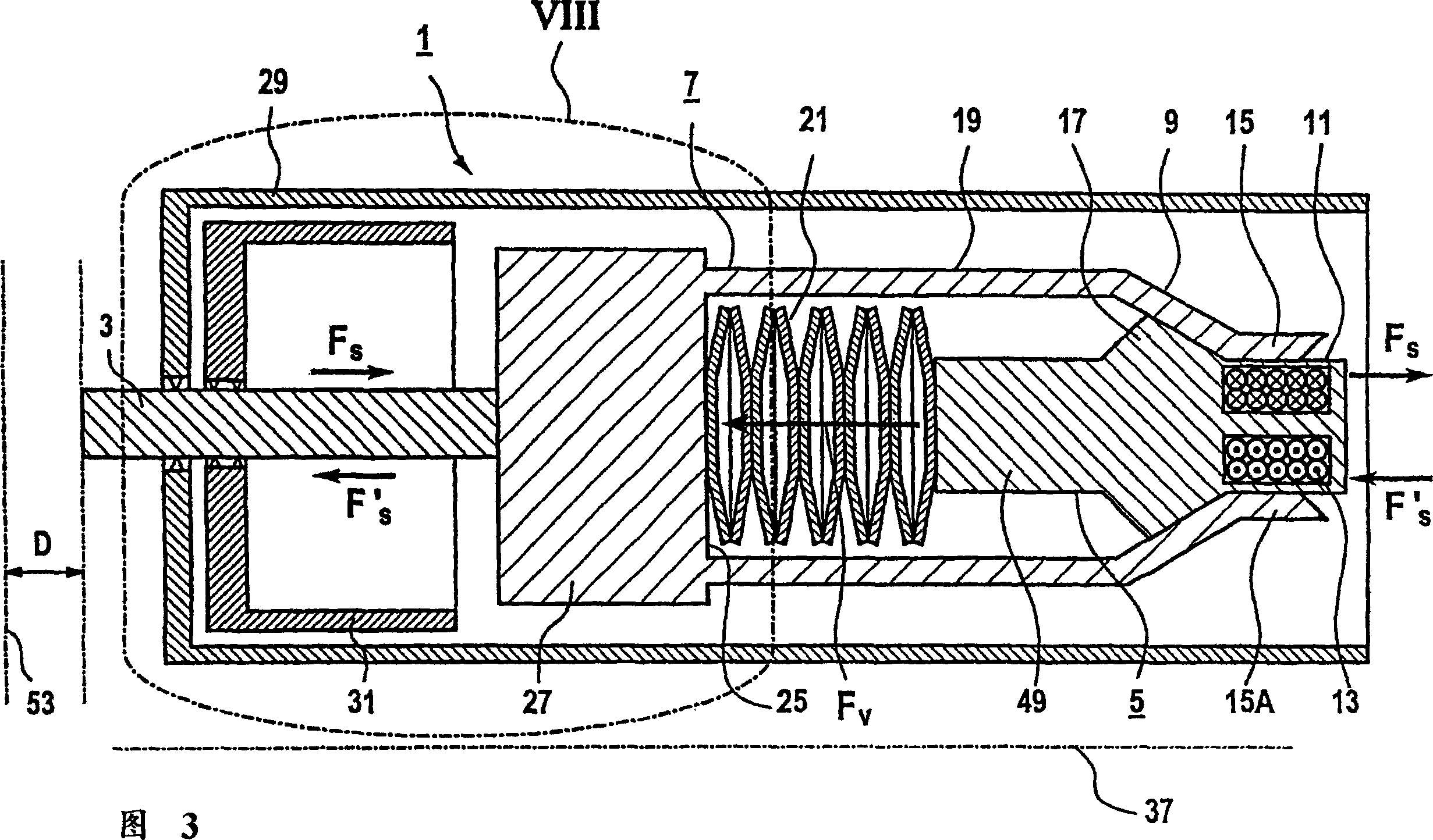
[0049] figure 1 A longitudinal sectional view of the adjusting mechanism 1 of a valve, in particular a turbine valve, is shown. The adjustment mechanism extends along a longitudinal axis 37, and along the axis 37 there are successively one for adjusting figure 1 Valve rod 3 , an energy storage device 7 and a drive element 5 in the opening position of the valve, not shown in detail. The drive part 5 , the energy storage device 7 and the valve rod 3 are here arranged at least partially in a housing 29 . The energy storage device has a spring element 21 , wherein the spring element 21 is assembled from a plurality of disk springs 23A, 23B arranged along a longitudinal axis 37 adjacent to each other. The driving part 5 is coupled to the valve stem 3 via an energy storage device 7 . The energy storage device 7 is coupled to the valve stem 3 via a damping piston 27 formed on the bottom 5 of the energy storage device 7 . To this end, the valve stem 3 is connected to the damping p...


PUM


Abstract

The invention relates to an actuator (1) for a valve, in particular a turbine valve, comprising a valve spindle (3), for adjustment of an opening position (D) for the valve and a drive piece (5) for the valve spindle (3). The drive piece (5) is connected to the valve spindle (3), by means of a storage device (7), which may be pre-tensioned to a particular pre-tensioned value (Fv) during a pre-tensioning process, in such a manner that, with a pre-tensioned storage device (7) the opening position (D) can be set without altering the value of the pre-tensioning (Fv). Said actuator (1) is particularly suitable for a valve on a steam turbine or a gas turbine. In a particularly preferred embodiment the actuator (1) comprises a hydraulic damping unit (61), integrated in a damping piston (27). Said damping unit permits a reliable end-travel damping for the valve, in particular in the case of rapid closure.

Description

technical field [0001] The invention relates to an adjusting mechanism for a valve, in particular a turbine valve, with a valve stem for adjusting the opening position of the valve and a drive element assigned to the valve stem. Background technique [0002] A turbine, in particular a steam turbine, usually has a considerable number of valves, which can be used, for example, as live steam valves, shut-off valves, bypass valves and quick shut-off valves. For this purpose, the opening position of each of these valves is used to regulate the respective material flow, gas flow or steam flow, and its opening position can be adjusted, for example, via a valve stem assigned to the respective valve. Such a valve stem is a component part of an adjusting mechanism assigned to the valve. In this respect, high demands are placed on the adjusting mechanism, especially with regard to the adjusting force and the adjusting speed. For example, for high reliability of the valve, the adjusti...

Claims


Application Information

Patent Timeline
Patent Type & Authority Patents(China)
IPC IPC(8): F16K31/00F16K31/06F01D25/00F01D17/10
CPCF16K31/003F16K31/06
Inventor 理查德·斯坦伯恩
Owner SIEMENS AG
Learn More