
Wiper device

A technology of wiper blade and wiper arm, applied in the field of wiper device, can solve the problem of separation of wiper blade and wiper arm, and achieve the effect of stable guidance

Inactive Publication Date: 2006-12-27
ROBERT BOSCH GMBH
View PDF1 Cites 0 Cited by
  • Summary
  • Abstract
  • Description
  • Claims
  • Application Information

AI Technical Summary

Problems solved by technology

However, when there is a lot of rain and / or the driving speed is very fast and when it is snowing, especially when it is snowing heavily, the force acting on the hinged connection from the wiper blade may exceed the stop holding capacity of the rubber elastic connection and make the Wiper blade separated from wiper arm

Method used


Image

  • Wiper device
  • Wiper device
  • Wiper device

Examples


Embodiment Construction

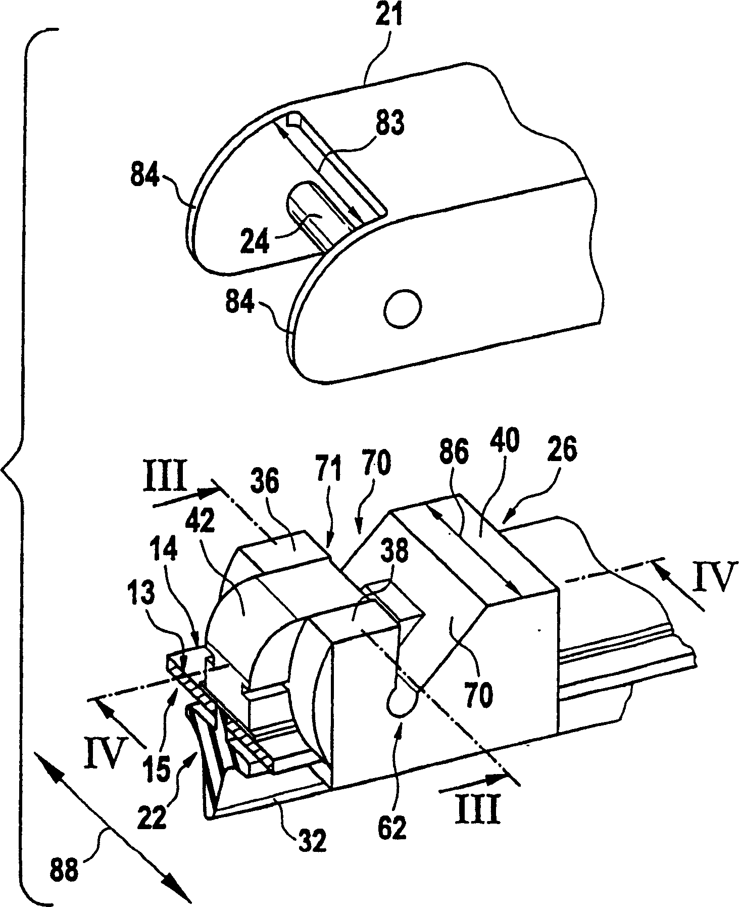
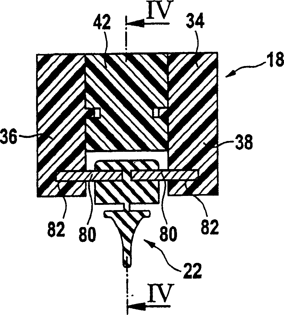
[0035] figure 1 and figure 2A wiper device 10 shown in has a wiper strip 12 with a strip-shaped elongated spring-elastic support element 14 . On the upper strip-shaped surface 13 of the support element facing away from the glass pane 16 to be wiped, a connecting device 18 whose surface abuts on the support element is arranged, by means of which connecting device the wiper strip 12 can be connected with one end on the vehicle. A driven wiper arm 20 attached to the wiper device is releasably connected to the body of the vehicle. An elongated rubber-elastic wiper blade 22 is arranged parallel to the longitudinal axis on the lower strip-shaped surface 15 of the carrier element 14 facing the glass pane 16 . Attached to the free end 21 of the wiper arm 20 is an articulation pin 24 serving as an arm-side connection, which is supported in a bearing seat of a wiper blade-side connection part 26 . The free end of the wiper arm 20 is loaded in the direction of the arrow 30 against th...


PUM


Abstract

A wiper system has a driveable wiper arm (20) guided at one end on the motor vehicle. A long-straggling wiper blade (12) capable of being placed against the window (16) with a wiper strip (22) is detachably hinge-mounted via a connection device (18) that has a pivot bolt (24) on the arm side. The axis of articulation of the pivot bolt extends substantially transversely to the longitudinal direction of the wiper blade in the working direction of the wiper system. The system includes a coupling part (26) on the wiper-blade side in a center section of the wiper blade (12) on its side opposite from the window (16) having a bore-like bearing receptacle for a pivot bolt (24). The bearing receptacle is provided with a bottleneck (94) capable of being expanded elastically to the diameter (92) of the pivot bolt.

Description

technical field [0001] A wiper device according to the invention has, in addition to a driven wiper arm, a wiper blade to be fastened to a free end of the wiper arm. The necessary connecting means have correspondingly designed mutually corresponding connecting means both on the arm side and on the blade side. Background technique [0002] In a known wiper device of this type (DE 23 13 689 A1), the wiper blade belonging to the wiper device or its connecting part has a guide channel open to the base body of the wiper blade, in which In the channel there is a fork-shaped safety stop spring that slides between a mounted position and a locked position. This safety catch spring is used to open or close a recess arranged in the connecting piece, which is a bearing recess for the wiper arm pivot pin. The safety lock spring is pretensioned against a rubber base body of the wiper blade, so that the friction between the rubber and the spring has to be overcome in order for the spring...

Claims


Application Information

Patent Timeline
IPC IPC(8): B60S1/40B60S1/38B60S1/42
CPCB60S1/4038B60S1/4041B60S1/38B60S1/3806B60S1/3849Y10T403/599Y10T403/602B60S1/40
Inventor P·德布洛克
Owner ROBERT BOSCH GMBH
Learn More