Eureka AIR delivers breakthrough ideas for toughest innovation challenges, trusted by R&D personnel around the world.

Unidirectional heat conduction apparatus

A one-way, heat pipe technology, applied in indirect heat exchangers, lighting and heating equipment, buildings, etc., can solve the problems of heat pipe efficiency loss and irreparability, and achieve the goal of avoiding temperature rise, maintaining long-term stability, and maintaining safe operation Effect

Inactive Publication Date: 2007-01-24
COLD & ARID REGIONS ENVIRONMENTAL & ENG RES INST CHINESE
View PDF5 Cites 0 Cited by
  • Summary
  • Abstract
  • Description
  • Claims
  • Application Information

AI Technical Summary

Problems solved by technology

However, since the heat pipe is buried inside the embankment, once the working fluid in the heat pipe leaks, the loss of heat pipe efficiency will not be repaired

Method used

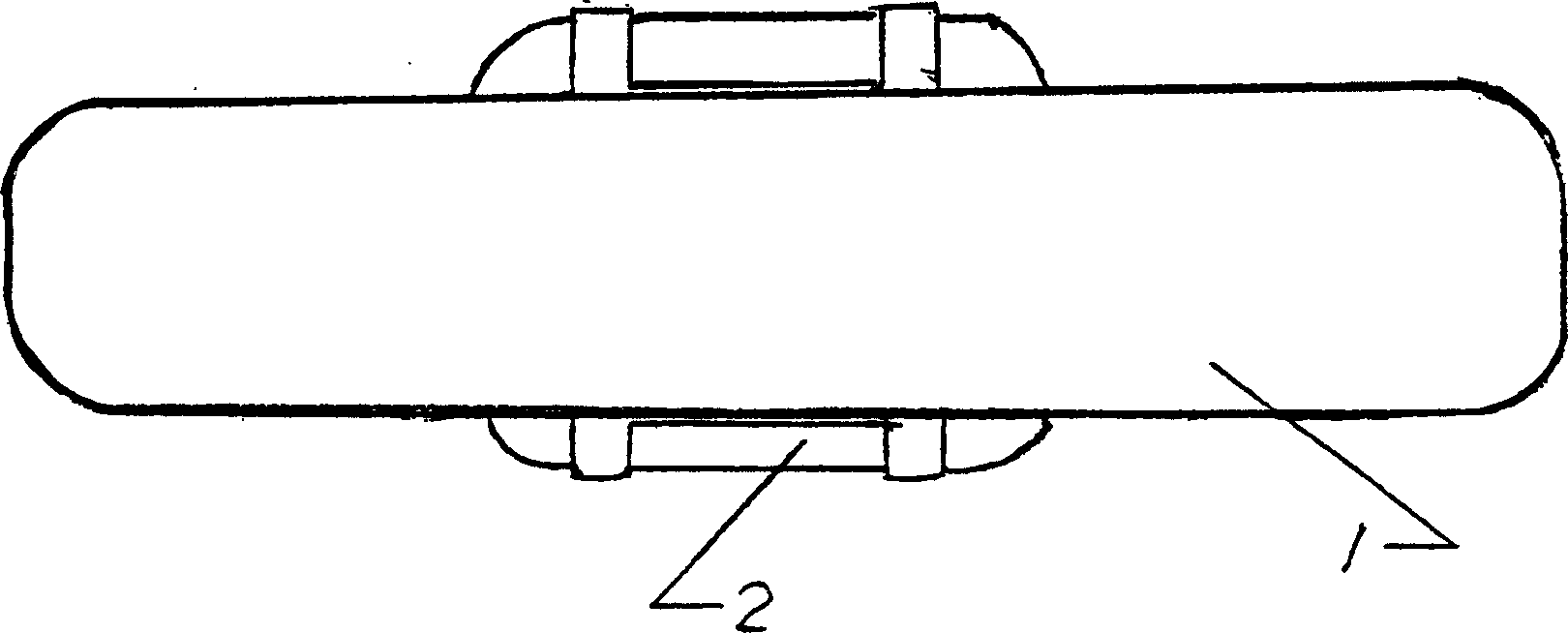
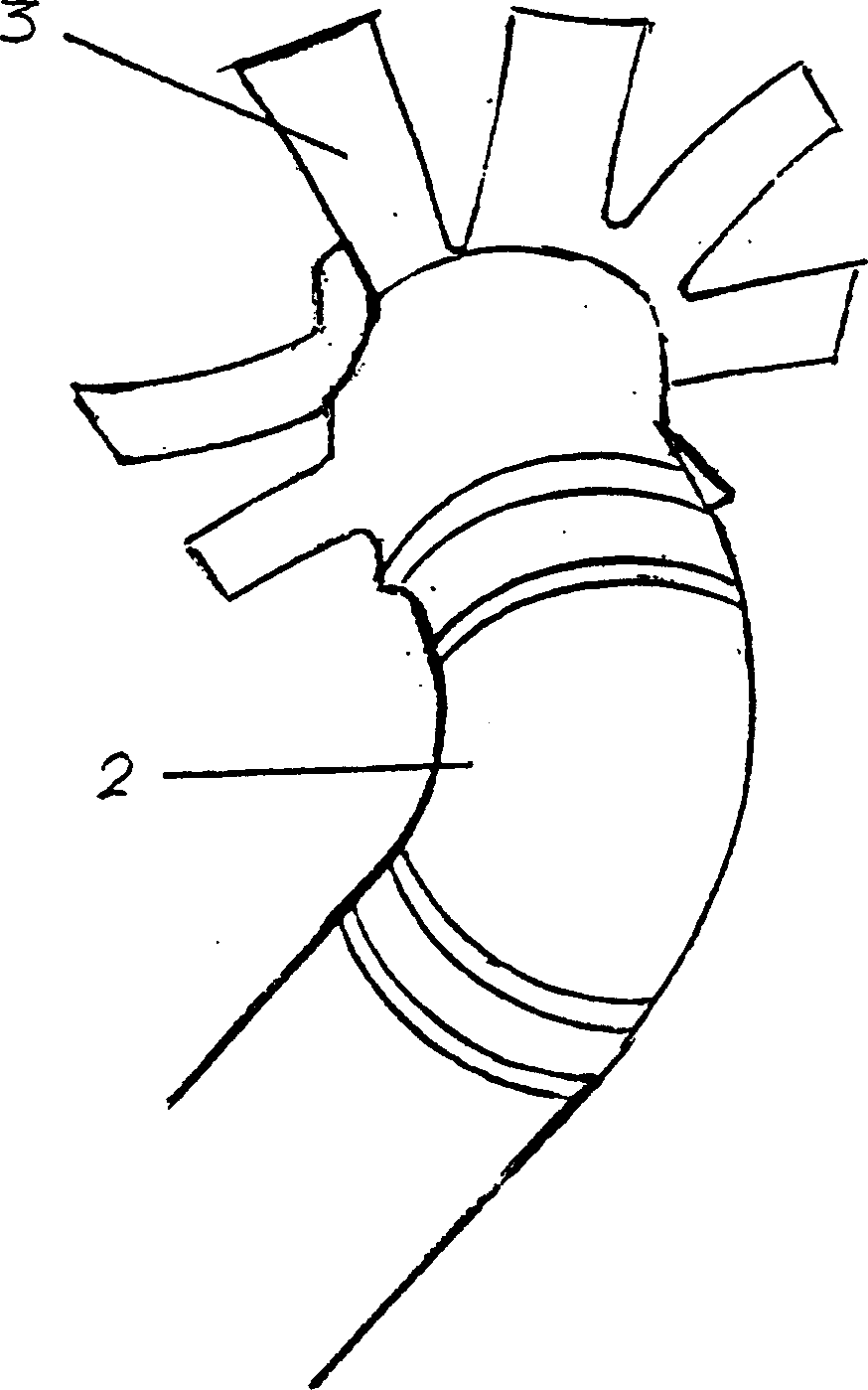

Image

  • Unidirectional heat conduction apparatus
  • Unidirectional heat conduction apparatus
  • Unidirectional heat conduction apparatus

Examples


Embodiment Construction

[0028]It can be seen from the above analysis that the heat conduction of the device depends on the flow of working fluid in the conduction tube. When air is used as the working medium in the conduction tube, the flow of sealed air in the conduction tube can be measured by the following method. That is, it can be indirectly judged whether the air is flowing or not by measuring the change of the air temperature inside the conduction pipe. For this method, when the device is in a heat-conducting environment, when the air in the conduction tube should be in a flowing state, the flowing air will continuously absorb heat at the lower hot end through convective heat exchange, and release heat at the upper cold end. During this process, the air temperature in the conduction tube should be lower than the ambient temperature outside the tube at the lower hot end, and the air temperature in the tube at the upper cold end should be higher than the ambient temperature outside the tube. An...


PUM


Abstract

This invention design carries on the railroad in many years frozen earth area, the road and in the project construction construction one kind of unidirectional heat conduction installment, it is by the thermal insulation material, the working substance carrier, the metal tube composes, the metal tube through the thermal insulation material and the working substance carrier nesting, encircles annular channel. Installs underground this installment level in in the certain position soil body; Using its unidirectional heat conduction performance, summer the external environment temperature is higher, the quantity of heat unceasingly spreads to in the soil body, this equipment may effectively prevent this part of thermal spreading to; Is lower in the winter external environment temperature, soil body unceasingly exothermic, flows through carrier the heavy working substance with the convection, enables lower part the soil body the quantity of heat to release. From this may effectively avoid many years frozen earth season activity the freezing and thawing to the roadbed and the project construction stable influence, causes on many years frozen earth the project construction stable establishment in a higher level.

Description

technical field [0001] The invention mainly relates to the effective protection of permafrost at the subgrade of roads and the permafrost at the bottom of building foundations in the construction of railways, highways and engineering buildings in permafrost regions, improving the stability of engineering buildings, and using natural cold energy for cooling in engineering buildings Cooling; or a device that uses natural heat in warm seasons in cold regions to store it underground to meet the needs of buildings or objects to maintain a relatively high temperature. Background technique [0002] The area of ​​permafrost in my country accounts for 22.3% of the country's land area, ranking third in the world, and the area of ​​high-altitude permafrost ranks the largest in the world. Human activities can easily induce changes in the permafrost environment, especially those caused by engineering technology factors. Because high-altitude permafrost regions tend to have steeper slope...

Claims


Application Information

Patent Timeline
Patent Type & Authority Patents(China)
IPC IPC(8): F28D15/00E02D27/35
Inventor 俞祁浩程国栋
Owner COLD & ARID REGIONS ENVIRONMENTAL & ENG RES INST CHINESE
Why Eureka
Eureka Blog
Learn More