
Cooling system for gas turbine

A technology of cooling system and cooling medium, which is applied in the field of manifold system and can solve the problems of large loss

Inactive Publication Date: 2007-02-07
GENERAL ELECTRIC CO
View PDF11 Cites 0 Cited by
  • Summary
  • Abstract
  • Description
  • Claims
  • Application Information

AI Technical Summary

Problems solved by technology

While gas turbines are typically air cooled, such as jet engines that use compressor discharge air to cool hot gas components, steam cooling has proven to be more effective in turbines for onshore power generation because of the relative Losses are not as great as those associated with extracting compressor discharge air for cooling purposes

Method used


Image

  • Cooling system for gas turbine
  • Cooling system for gas turbine
  • Cooling system for gas turbine

Examples


Embodiment Construction

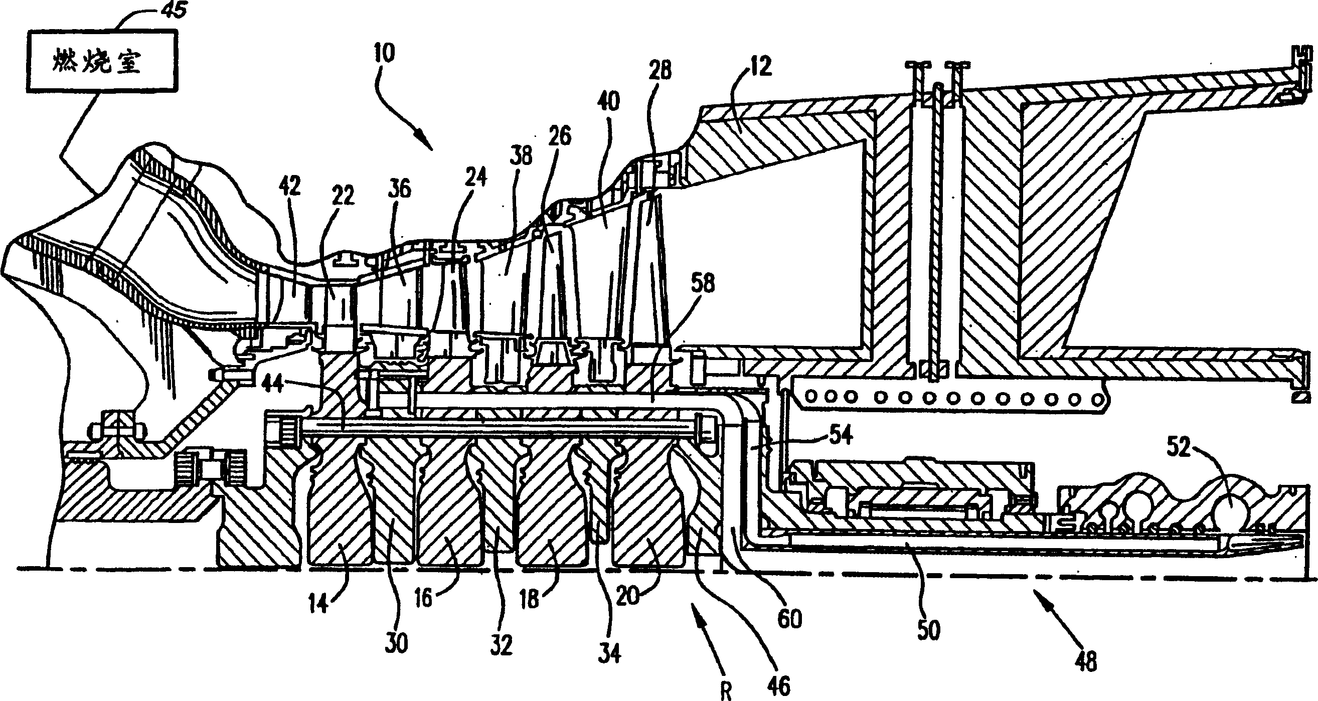
[0021] Referring now to the attached drawings especially figure 1 , there is shown a turbine section indicated generally at 10 which incorporates a preferred embodiment of the present invention. The turbine section 10 includes a turbine housing 12 surrounding a turbine rotor R. As shown in FIG. The rotor R in this example comprises four successive stages comprising impellers 14, 16, 18 and 20 with a plurality of circumferentially spaced buckets or blades 22, 24, 26 and 28, respectively. The impellers are arranged alternately between the spacers 30 , 32 and 34 . The outer edges of the spacers 30 , 32 and 34 are radially aligned with a plurality of stator buckets or nozzles 36 , 38 and 40 , with a first set of nozzles 42 forward of the first bucket 22 . It will therefore be appreciated that a four stage turbine is shown where the first stage includes the nozzle 42 and buckets 22, the second stage includes the nozzle 36 and buckets 24, the third stage includes the nozzle 38 and...


PUM


Abstract

A plurality of arcuate circumferentially spaced supply and return manifold segments are arranged on the rim of a rotor for respectively receiving and distributing cooling steam through exit ports for distribution to first and second-stage buckets and receiving spent cooling steam from the first and second-stage buckets through inlet ports for transmission to axially extending return passages. Each of the supply and return manifold segments has a retention system for precluding substantial axial, radial and circumferential displacement relative to the rotor. The segments also include guide vanes for minimizing pressure losses in the supply and return of the cooling steam. The segments lie substantially equal distances from the centerline of the rotor and crossover tubes extend through each of the segments for communicating steam between the axially adjacent buckets of the first and second stages, respectively.

Description

[0001] This invention was made with Government support under Contract No. DE-FC21-95MC31176 awarded by the Department of Energy. The government has certain rights in this invention. technical field [0002] The present invention generally relates to a gas turbine for generating electricity using a closed cooling path for flowing a cooling medium, such as steam, to cool components in a high temperature gas path and to return spent cooling medium to the Some such as waste heat recovery steam generators used in combined cycle systems. More specifically, the present invention relates to a manifold system for supplying cooling medium to the buckets of first and second stage impellers and for sending spent cooling medium from the buckets back to waste heat recovery generation device. Background technique [0003] Cooling components in the path of high temperature gases, such as the buckets of gas turbines, has been proposed in the past and has been found to be particularly effec...

Claims


Application Information

Patent Timeline
Patent Type & Authority Patents(China)
IPC IPC(8): F02C7/12F01D5/08F01D5/06F02C7/18
CPCF01D5/084F01D5/085Y02T50/676F05D2260/2322F05D2260/205F01D5/08Y02T50/60F01D5/06
Inventor I·D·威尔逊S·A·萨拉马N·J·拜利纳
Owner GENERAL ELECTRIC CO
Learn More