Supercharge Your Innovation With Domain-Expert AI Agents!

Liquid crystal display device

A liquid crystal display device, liquid crystal module technology, applied in the direction of optics, instruments, electrical components, etc., can solve problems such as damage

Inactive Publication Date: 2007-02-21
TPO DISPLAY
View PDF7 Cites 0 Cited by
  • Summary
  • Abstract
  • Description
  • Claims
  • Application Information

AI Technical Summary

Problems solved by technology

[0006] In view of this, the purpose of the present invention is to provide an improved liquid crystal display device to overcome the above-mentioned problems caused by high-voltage electrostatic discharge phenomenon

Method used


Image

  • Liquid crystal display device
  • Liquid crystal display device
  • Liquid crystal display device

Examples


no. 1 example

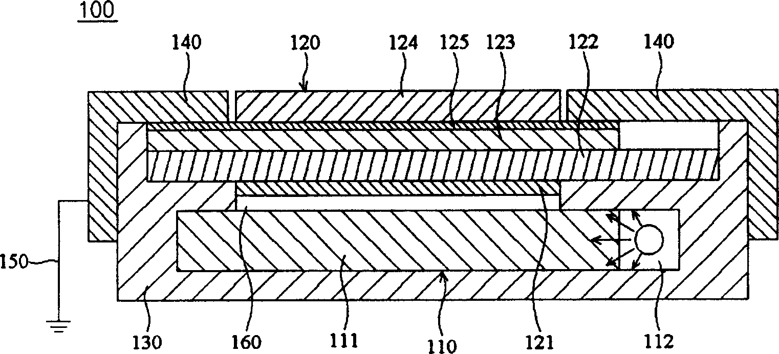
[0052] see figure 2 The liquid crystal display device 100 of this embodiment mainly includes a light guide module (light guide module) 110, a liquid crystal module (LCD module) 120, a frame (frame) 130, a plurality of conductive frames (bezel) 140 and a grounding assembly (grounding element) 150.

[0053] The light guide module 110 has a light guide panel 111 and a light source 112 , and the light source 112 is disposed on a side of the light guide panel 111 . The liquid crystal module 120 is disposed on the light guide module 110 , and there is a gap 160 between the liquid crystal module 120 and the light guide module 110 . The liquid crystal module 120 is composed of a first polarizer (first polarizer) 121, a first glass substrate (first glass substrate) 122, a second glass substrate (second glass substrate) 123 and a second polarizer (second polarizer) 124 composed of. Most particularly, there is a conductive layer 125 in the liquid crystal module 120 . As mentioned ab...

no. 2 example

[0058] In this embodiment, the components that are the same as those in the first embodiment are marked with the same reference numerals.

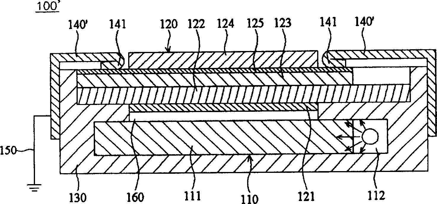
[0059] see image 3 The liquid crystal display device 100' of this embodiment mainly includes a light guide module 110, a liquid crystal module 120, a frame 130, a plurality of conductive frames 140' and a grounding component 150.

[0060] The difference between this embodiment and the first embodiment lies in the difference in the structure of the conductive frame, and the rest of the component structures and configurations are the same as the first embodiment. Therefore, in order to make the description clearer and easier to understand, it is omitted. Same narrative.

[0061] still refer to image 3 In order to reduce the weight and thickness of the liquid crystal display device 100', in this embodiment, the thickness of the conductive frame 140' is reduced (half of the thickness of the conductive frame 140 in the first embodiment). A...


PUM


Abstract

The invention discloses a liquid crystal displaying equipment, it includes an optical leading module, a liquid crystal module, a frame, an electric frame and a grounded groupware. The liquid crystal module is set on the optical leading module, and it has a conducting layer. The frame covers the optical leading module and the liquid crystal module. The electric frame is fixed on the frame and is connected to the conducting layer of the liquid crystal module. The grounded groupware is connected to the electric frame.

Description

technical field [0001] The present invention relates to a liquid crystal display device, in particular to a liquid crystal display device capable of preventing damage due to electrostatic discharge. Background technique [0002] In general, conventional liquid crystal displays generally have a similar structure. Such as figure 1 As shown, a conventional liquid crystal display 1 mainly includes a light guide module (light guide module) 11, a lower polarizer (lower polarizer) 12, a lower glass substrate (lower glass substrate) 13, an upper glass substrate (upper glass substrate) 14. An upper polarizer (upper polarizer) 15, a frame (frame) 16 and two metal frames (bezel) 17. In particular, the lower polarizer 12 , the lower glass substrate 13 , the upper glass substrate 14 and the upper polarizer 15 can be referred to as a liquid crystal module (LCD module) 10 . The light guide module 11 also has a light guide panel 11a and a light source 11b. The lower polarizer 12 is disp...

Claims


Application Information

Patent Timeline
Patent Type & Authority Patents(China)
IPC IPC(8): G02F1/1333H01L21/00G02F1/1345
Inventor 麦哲魁
Owner TPO DISPLAY
Features
  • R&D
  • Intellectual Property
  • Life Sciences
  • Materials
  • Tech Scout
  • Unparalleled Data Quality
  • Higher Quality Content
  • 60% Fewer Hallucinations
Learn More