Laminated piezoelectric transducer

A piezoelectric transformer, layered technology, applied in piezoelectric/electrostrictive/magnetostrictive devices, circuits, electrical components, etc. Effect

Inactive Publication Date: 2001-07-18
PANASONIC CORP
View PDF0 Cites 8 Cited by
  • Summary
  • Abstract
  • Description
  • Claims
  • Application Information

AI Technical Summary

Problems solved by technology

Since this structure is to set the output side (secondary) external electrode 113 in the direction perpendicular to the vibration direction of the laminated piezoelectric body, its vibration is weakened, and the efficiency of energy conversion is also low.

Method used


Image

  • Laminated piezoelectric transducer
  • Laminated piezoelectric transducer
  • Laminated piezoelectric transducer

Examples


no. 1 Embodiment

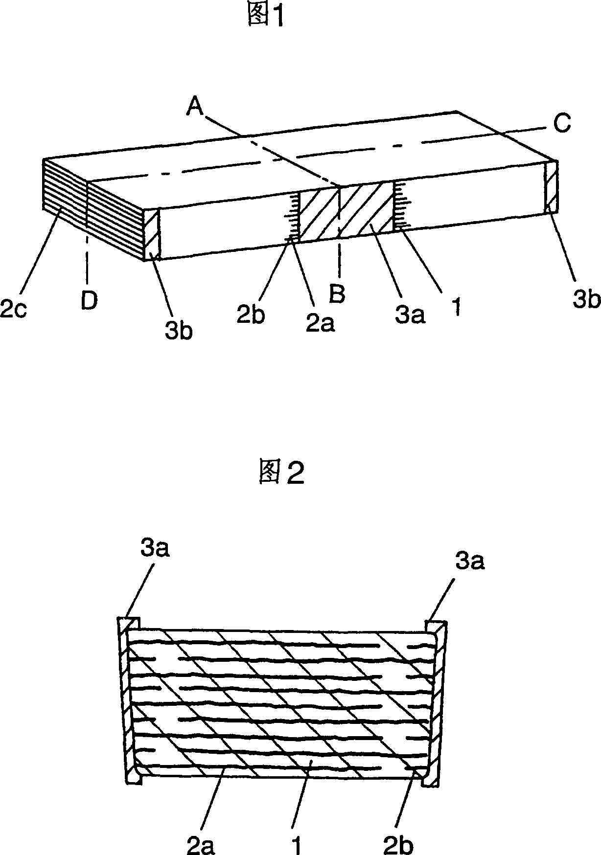
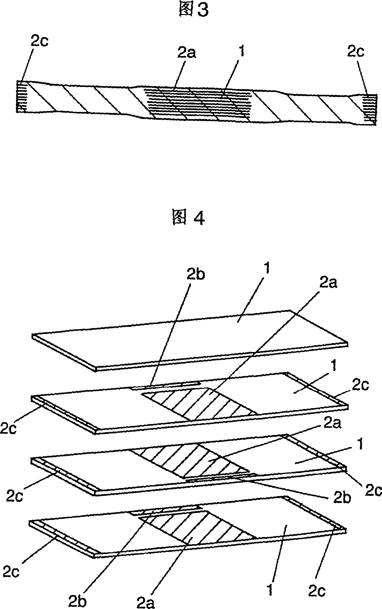
[0014] The manufacturing flow of the laminated piezoelectric transducer shown in FIG. 1 will be described with reference to FIGS. 2 to 5 .

Embodiment 1

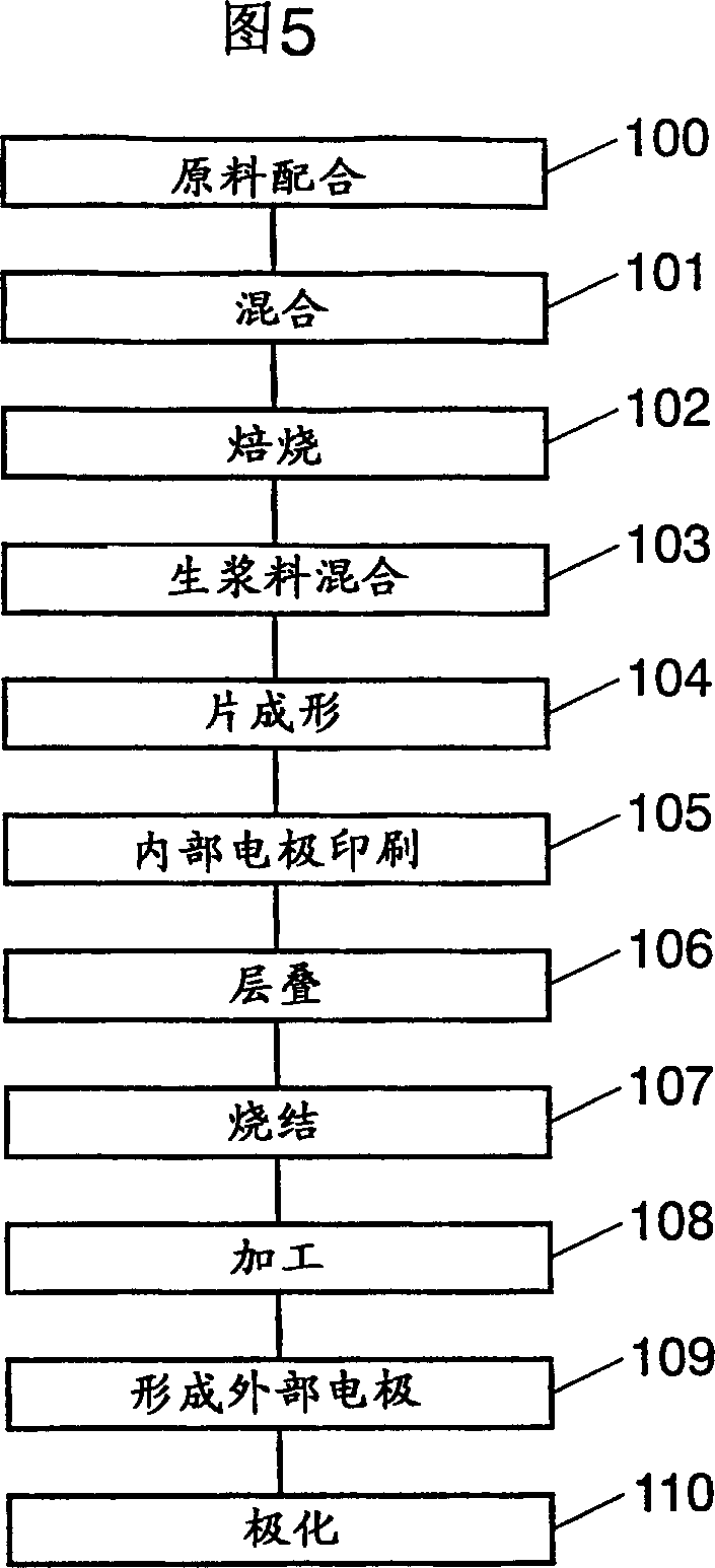
[0015] The multilayer piezoelectric transducer of Example 1 is composed of a ceramic layer 1, primary internal electrodes 2a and 2b, a secondary internal electrode 2c, a primary external electrode 3a, and a primary external electrode 3b. Its manufacturing method can be described based on the manufacturing flow chart shown in FIG. 5 .

[0016] First, PbO, ZrO, which are used in the manufacture of lead zirconate titanate-based piezoelectric materials, 2 、TiO 2 As the main material, auxiliary materials are added according to the specified ratio (step 100), and then mixed in the ball mill according to the set time (step 101).

[0017] Next, roast the mixed raw material powder (step 102), add organic binding material, plasticizer, and organic solvent in proportion, and carry out raw slurry mixing (step 103), and obtain the raw slurry for sheet forming.

[0018] Thereafter, the above-mentioned green slurry is applied by the doctor blade method to form a sheet (step 104), and a cer...

no. 2 Embodiment

[0028] Fig. 6 is a perspective view of a second embodiment of the laminated piezoelectric transducer. In Example 1, the external electrodes 3a and 3b were formed only on the side surfaces in the width direction of the laminate, but in this embodiment, the external electrodes 3a and 3b are provided not only on the side surfaces of the laminate but also on the upper and lower surfaces of the laminate.

[0029] According to the structure of this embodiment, the strength of the laminate increases as the adhesive strength between the laminate and the external electrodes 3a, 3b increases.

[0030] Furthermore, the existence of the external electrodes 3a, 3a also polarizes the ceramic layer 1 constituting the outermost layer on the upper and lower surfaces of the laminated body, thereby improving the boosting ratio. In consideration of increasing the boosting ratio, it is desirable to make the external electrodes 3a, 3b as large as possible on the surface of the laminated body.


PUM


Abstract

A laminated piezoelectric transformer according to the present invention comprises (a) a laminated body formed by laminating a plurality of ceramic layers and a plurality of internal electrodes and (b) a plurality of external electrodes electrically connected with the internal electrodes and disposed on the surface of the laminated body. Further, the internal electrodes of the laminated piezoelectric transformer of the invention are characterized by having a plurality of primary internal electrodes positioned at the middle portion along the longitudinal direction of the laminated body and a plurality of secondary internal electrodes positioned at both end portions of the laminated body. By virtue of this configuration of the invention, the polarization volume on the secondary side can be enlarged and, therefore, the laminated piezoelectric transformer of the invention can step up voltages at high energy conversion efficiency.

Description

technical field [0001] The invention relates to a laminated piezoelectric transformer, which can be used in cold-cathode tube inverting circuits of electronic instruments such as PCs, portable information terminals, mobile video, etc. The role of light. In addition, it can also be used in other boost circuits. Background technique [0002] Next, a conventional method for manufacturing a multilayer piezoelectric transducer will be described. Fig. 18 is a perspective view of a conventional multilayer piezoelectric transducer. [0003] First, a rectangular laminate in which ceramic layers 111 and input-side internal electrodes are alternately laminated is formed. In this case, the input-side (primary) internal electrodes are naturally formed by alternately exposing on two opposite side surfaces at the central position in the longitudinal direction of the laminated body. [0004] Next, external electrodes 112 are formed on both sides of the laminate where the internal electr...

Claims


Application Information

Patent Timeline
Patent Type & Authority Applications(China)
IPC IPC(8): H01L41/047H01L41/083H01L41/107
CPCH01L41/047H01L41/0477H01L41/0471H01L41/187H01L41/0831H01L41/107H01L41/083H10N30/871H10N30/877H10N30/501H10N30/50H10N30/40H10N30/853
Inventor 奥田和弘后藤泰司南诚一山口朋一川村聪河野国敏福岛宽
Owner PANASONIC CORP
Why Eureka
Try Eureka