Optical gate protection circuit for light conducting system of laser processing equipment

A light guide system and laser processing technology, applied in circuits, lasers, laser parts, etc., can solve the problems of poor reliability, complicated adjustment, and cumbersome work.

Active Publication Date: 2007-03-14
CHINA FIRST AUTOMOBILE
View PDF5 Cites 0 Cited by
  • Summary
  • Abstract
  • Description
  • Claims
  • Application Information

AI Technical Summary

Problems solved by technology

Using PLC to design the shutter protection circuit requires the use of relays, time-delay relays, proximity switches, etc., and multiple programs must be compiled and controlled by a microprocessor. Therefore, the work is cumbersome, the reliability is poor, and the adjustment is also complicated. PLC is also more expensive

Method used


Image

  • Optical gate protection circuit for light conducting system of laser processing equipment
  • Optical gate protection circuit for light conducting system of laser processing equipment

Examples


Embodiment Construction

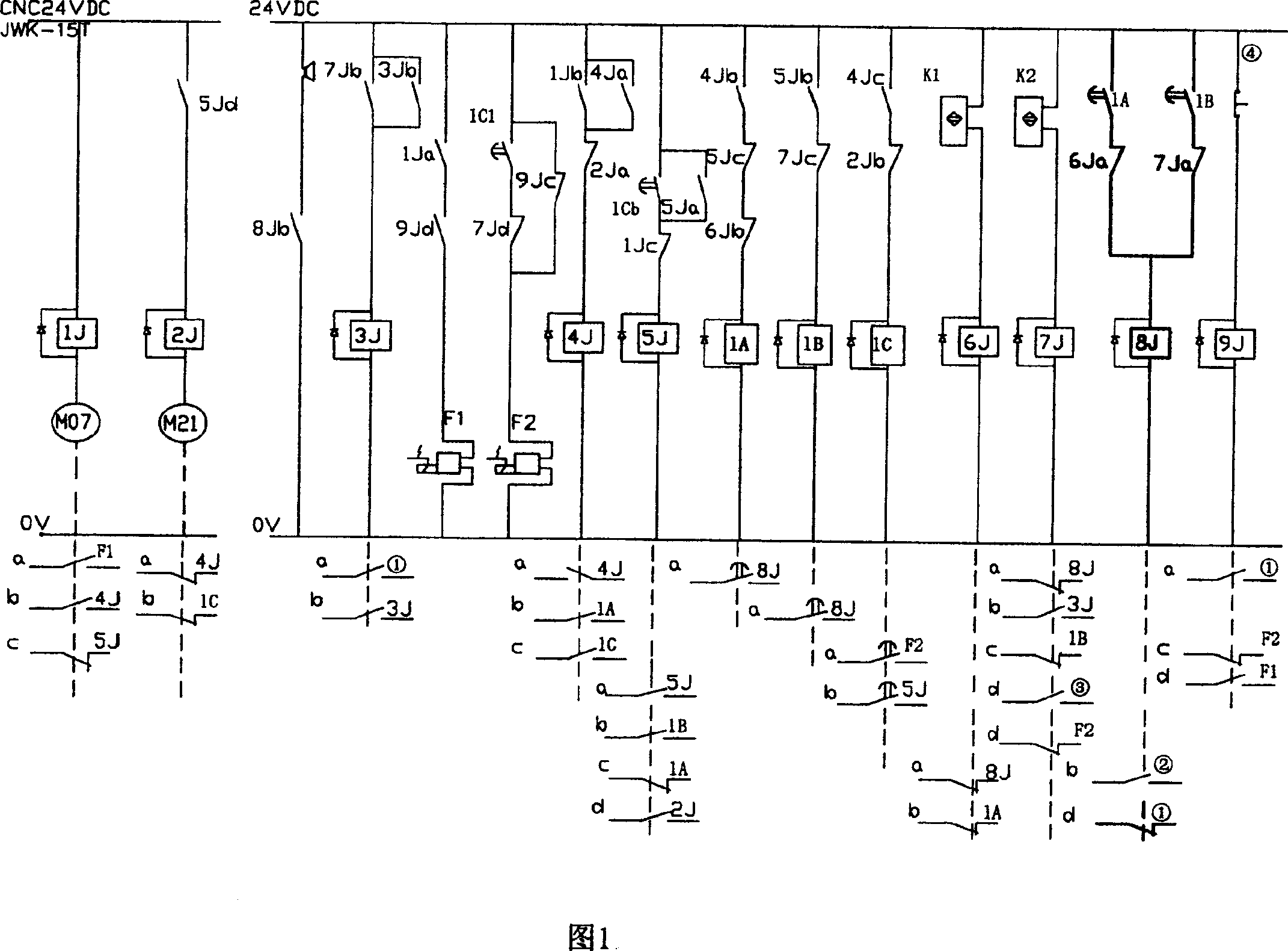
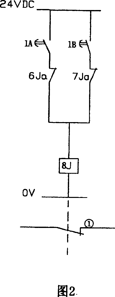
[0008] Combined with the accompanying drawings below, and use the 1500W, wavelength 10.6μCO for processing an automobile part 2 Taking a laser as an example, the optical gate protection circuit of the present invention will be described in detail.

[0009] As shown in Figure 1 and Figure 2, the light gate protection circuit of the laser processing equipment light guide system of the present invention is mainly composed of a delay relay 1A, a delay relay 1B, a first common relay 6J, a second common relay 7J, and a relay 8J. The normally open contact of delay relay 1A is connected in series with the normally closed contact 6Ja of the first common relay 6J; the normally open contact of another time delay relay 1B is connected in series with the normally closed contact 7Ja of the second common relay 7J; The above two series circuits are connected in parallel and connected in series with relay 8J; the other end of relay 8J is connected with 0V line, and the other end of delay relay...


PUM


Abstract

This invention discloses an optical gating protecting circuit of laser device light-conductive system, which is to cascade normally opened contact of time-delay relay (LA) with normally-closed contact (6Ja) of common relay and to cascade another normally opened contact of time-delay relay (LB) with normally-closed contact (7Ja) of common relay and to cascade; then to parallel connect the above two cascaded circuits then to cascade with relay (8J); finally to parallel connect the whole above circuit between 24VDC and V line of optical gating control circuit and one normally-closed contact (1) of relay (8J) is cascaded in starting returning circuit of laser device.

Description

technical field [0001] The invention relates to a light guide system of laser processing equipment, in particular to a light gate protection circuit of the light guide system of laser processing equipment. Background technique [0002] The optical gate is an important part of high-power laser processing equipment. Since the laser beam has a strong energy density, its transmission must be controlled by the optical gate. When the optical gate is opened, the laser beam passes through, and when the optical gate is closed, the laser beam is truncate. Personal injury and equipment damage may result if the shutter fails. In order to carry out laser processing safely, the control of the shutter must be safe and reliable. Once the shutter of the laser beam fails, a control circuit is required to automatically shut down the laser and stop the laser output. [0003] At present, the shutter protection of laser processing equipment is generally realized by industrial programmable logic...

Claims


Application Information

Patent Timeline
Patent Type & Authority Patents(China)
IPC IPC(8): G02B26/00H01S3/10G05B19/04
Inventor 郑培和姚远魏伟喻皓淳秦芳孔德举
Owner CHINA FIRST AUTOMOBILE
Why Eureka
Try Eureka