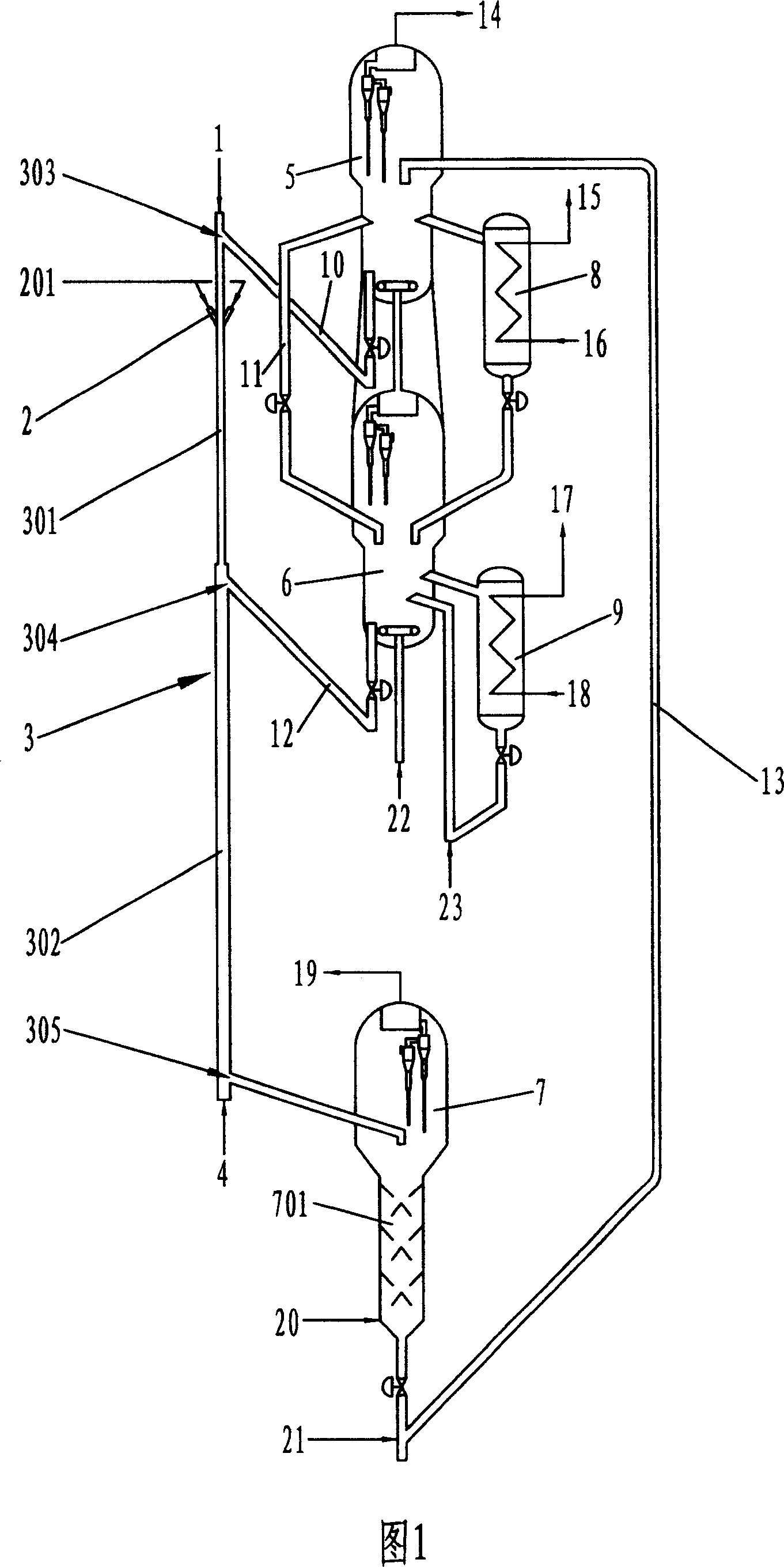
Down pipe type catalytic cracking method and apparatus
A tubular catalytic and catalytic cracking technology, which is applied in catalytic cracking, cracking, petroleum industry, etc., can solve the problems of catalytic reaction degree reduction, catalyst and oil gas back-mixing, oil gas and catalyst back-mixing, etc., and achieve the improvement of catalytic reaction degree, The effect of improving catalyst activity and increasing the ratio of catalyst to oil
- Summary
- Abstract
- Description
- Claims
- Application Information
AI Technical Summary
Problems solved by technology
Method used
Image
Examples
Embodiment 1
[0050] This example illustrates the results of catalytic cracking using Daqing atmospheric residue as raw material. The distance from the catalyst inlet of the second reaction section (that is, the catalyst inlet in the middle of the downcomer reactor) to the feed oil inlet at the top of the downcomer reactor is 50% of the total length of the actual reaction section of the downcomer reactor.
[0051] The operating conditions adopted in this embodiment are: the regeneration temperature of the first regenerator is 700°C, the carbon content of the regenerated semi-regenerated catalyst is 0.25w%, and the semi-regenerated catalyst enters the first reaction section from the catalyst inlet at the top of the downward tubular reactor. The temperature of the regenerated catalyst was 700°C. The regeneration temperature of the second regenerator is 500°C, the carbon content of the regenerated catalyst is 0.05w%, and the temperature of the regenerated catalyst entering the second reaction ...
Embodiment 2
[0055] In Example 2, Daqing atmospheric residual oil is still used as the raw material, except that the distance from the catalyst inlet of the second reaction section of the downward tubular reactor to the feedstock oil inlet at the top of the downward tubular reactor is the total length of the actual reaction section of the downward tubular reactor. 40%. The residence time of oil and gas in the first reaction section is 0.8 seconds, and the residence time in the second reaction section is 1.6 seconds; the agent-oil ratio of the first reaction section is 6.6, and the agent-oil ratio of the second reaction section is 14.2. All the other operating conditions are the same as in Example 1. The catalytic cracking results are also listed in Table 2.
[0056] Due to the longer oil and gas residence time in the second reaction section of Example 2, the degree of secondary reaction increases. The yield of liquefied gas increased a lot, and the yield of gasoline and diesel was lower ...
Embodiment 3
[0058] This example illustrates the results of catalytic cracking using Zhongyuan Atmospheric Residue as raw material. The distance from the catalyst inlet of the second reaction section to the feed oil inlet at the top of the downcomer reactor is 50% of the total length of the actual reaction section of the downcomer reactor.
[0059]The operating conditions adopted in this embodiment are: the regeneration temperature of the first regenerator is 705°C, the carbon content of the regenerated semi-regenerated catalyst is 0.22w%, and the semi-regenerated catalyst enters the first reaction section from the top catalyst inlet of the down-flow tubular reactor. The temperature of the regenerated catalyst was 705°C. The regeneration temperature of the second regenerator is 510°C, the carbon content of the regenerated catalyst is 0.05w%, and the temperature of the regenerated catalyst entering the second reaction section from the catalyst inlet in the middle of the downtube reactor is ...
PUM
 Abstract
Description
Claims
Application Information
 - R&D
- Intellectual Property
- Life Sciences
- Materials
- Tech Scout
- Unparalleled Data Quality
- Higher Quality Content
- 60% Fewer Hallucinations
Browse by: Latest US Patents, China's latest patents, Technical Efficacy Thesaurus, Application Domain, Technology Topic, Popular Technical Reports.
© 2025 PatSnap. All rights reserved.Legal|Privacy policy|Modern Slavery Act Transparency Statement|Sitemap|About US| Contact US: help@patsnap.com

