Grinding drum and stirring mill of grinding and crushing machinery

A grinding drum and mechanical technology, applied in the field of grinding drums and stirring mills, can solve the problem of inability to precisely control particle size distribution, etc., and achieve the effect of improving grinding efficiency

Active Publication Date: 2007-05-23
毕舒
View PDF6 Cites 0 Cited by
  • Summary
  • Abstract
  • Description
  • Claims
  • Application Information

AI Technical Summary

Problems solved by technology

The material can be a slurry or a dry powder. The agitator shaft drives the medium and the material to rotate. The material in the cylinder and the medium gradually become thinner by collision and friction with each other. However, the original particle size of the material cannot be completely the same, and the cylinder body Most of them are cylindrical, so the external stress on the material in the stirring mill is the same as the grinding method, so that the final particle size distribution of the material cannot be concentrated in a small range, either under-grinding or over-grinding, and the particle size distribution cannot be accurately controlled.

Method used


Image

  • Grinding drum and stirring mill of grinding and crushing machinery
  • Grinding drum and stirring mill of grinding and crushing machinery
  • Grinding drum and stirring mill of grinding and crushing machinery

Examples


Embodiment 1

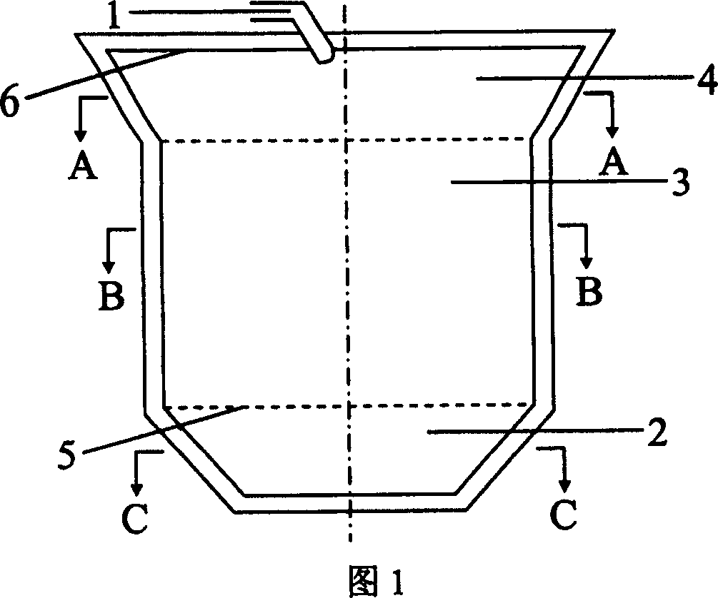
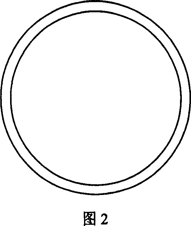
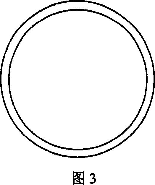
[0020] Example 1. A grinding cylinder of a grinding and pulverizing machine. With reference to Figures 1 to 4, the cylinder is cylindrical, and a discharge port 1 is provided near the center of the end surface at one end of the cylinder. The cylinder includes three parts with different structures, which are far away from A section of the discharge port 1 is the rotating speed section 2. This section has such a structure that the cross section of the inner wall is a regular hexagon, the longitudinal section is a trapezoid, and the side 5 close to the discharge port 1 is the long base; The inner wall is cylindrical; the part 4 located at the end of the discharge port has such a structure, the cross section of the inner wall is circular, the longitudinal section is trapezoidal, and the side 6 close to the discharge port 1 is the long bottom side.

[0021] In the above-mentioned embodiment, the cross-sectional profile of the inner wall of the rotating transmission section 2 may also b...

Embodiment 2

[0022] The second embodiment, an agitating mill, combined with Fig. 7, includes a grinding drum 7, a transmission mechanism 8 and a rotating spindle 9. The grinding drum has the structure in the first embodiment, and the feed port 10 is arranged opposite to the discharge port. At one end, the rotating main shaft 8 is arranged in the cylinder axially, and the transmission mechanism 8 drives the rotating main shaft 9 to rotate.

[0023] The specific working process: add water to the material to make a slurry with a solid content of 70%-75%, and use a pump (not shown) to send it to the inlet 10 at the bottom of the barrel. The inside of the mill barrel is driven by the rotating spindle 9 to drive the disc (not shown). Draw) High-speed rotation (1200-3000 rpm) produces strong centrifugal shearing force and squeezing collision force. The slurry rises from the bottom of the cylinder to the top discharge port 1 under a certain pressure.

[0024] When the material is in the lower part 2 o...


PUM


Abstract

The invention discloses a cylindrical barrel of grinding machine, in which the shaft of the grinding machine can be set to stirring. One end of the barrel is set a discharge hole, and off a certain distance from the hole there is a rotating speed transmission span, where the distance from the point on the inwall lateral section to the center of the rotating axis are different, which makes the powder rotating in the lateral section in variably velocity. Also, the invention relates to a stirring grinder, including a grinding barrel, a actuating mechanism and a rotating chief axis, wherein the barrel has the said structure, and the rotating chief axis is set inside the barrel along the barrel axis, the actuating mechanism drives the rotating chief axis to rotate. The polygonal structure off the discharge hole of the invention makes the shearing, compression, collision in the different sections of the same barrel, which homologous to the grinding process with several device and circulation: shearing, compression, again shearing, again compression.

Description

【Technical Field】 [0001] The invention relates to the grinding and crushing of materials, in particular to a grinding cylinder and a stirring mill of a grinding and crushing machine. 【Background technique】 [0002] At present, the widely used powder preparation machinery at home and abroad is a ball mill. The traditional ball mill uses the rotation of the barrel of the ball mill to bring the ball mill in the barrel to a certain height to store energy. During the falling process of the ball mill, an impact force is formed to hit the material to achieve the effect of crushing the material. This powder preparation method has simple equipment, and can obtain powder with a particle size that meets the requirements by lengthening the working time. Another feature is uniform mixing. Its obvious disadvantages are large area, high energy consumption, low production efficiency, and coarse powder particle size. [0003] In addition, there are traditional ultra-fine equipment, which can be c...

Claims


Application Information

Patent Timeline
Patent Type & Authority Patents(China)
IPC IPC(8): B02C17/18B02C17/16
Inventor 毕舒
Owner 毕舒
Why Eureka
Try Eureka