High speed rail vehicle capable of adjusting pressure on ground

A technology for high-speed rails and vehicles, applied in railway vehicles, motor vehicles, and passenger cars, etc., can solve the problems of increased line investment, large line investment, and low friction pressure of driving wheels, and achieves low line investment, fast construction, and operating costs. low effect

Inactive Publication Date: 2007-06-20
李孝龙
View PDF5 Cites 0 Cited by
  • Summary
  • Abstract
  • Description
  • Claims
  • Application Information

AI Technical Summary

Problems solved by technology

[0002] The friction pressure (adhesion force) between the wheels and the rails of the current high-speed rail vehicles mainly depends on the self-weight of the traction locomotive. As the speed of the train increases, the friction pressure between the wheels and the rails also decreases, causing the speed to be affected. However, the driving safety of the vehicle is greatly affected due to the reduction of the friction pressure. Although the friction pressure between the wheel and the rail in the "Intercity High-speed Light Rail Transit" with the application number 01141380.8 has been greatly improved, However, because the setting of the door frame and the top rail on the track beam objectively causes the vehicle to be inconvenient for cargo transportation, and the door frame and the top rail also increase the investment of the line; and the application number is "High-speed straddle rail vehicle" In the vehicle, the driving friction pressure of the vehicle is provided by the pressure device installed under the conductive wheel in the vehicle. Since the space under the conductive wheel is small, the pressure device is also small, and the friction pressure provided to the driving wheel in the vehicle is also small, which is difficult Guarantee the high frictional pressure required when the vehicle runs at high speed; at the same time, because it is driven by a linear motor in the currently applicable maglev train, the investment in its line is large and cannot be widely used

Method used


Image

  • High speed rail vehicle capable of adjusting pressure on ground
  • High speed rail vehicle capable of adjusting pressure on ground
  • High speed rail vehicle capable of adjusting pressure on ground

Examples


Embodiment 1

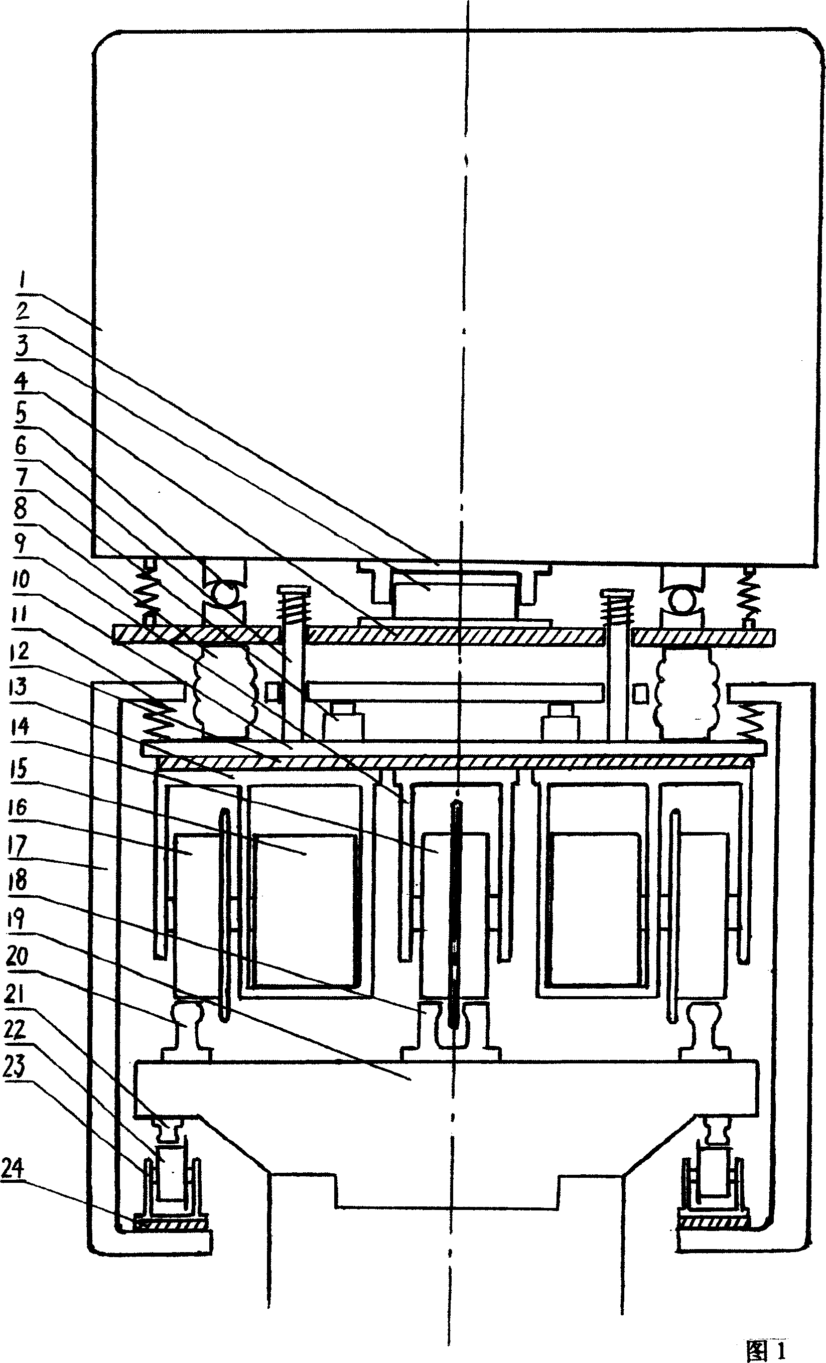
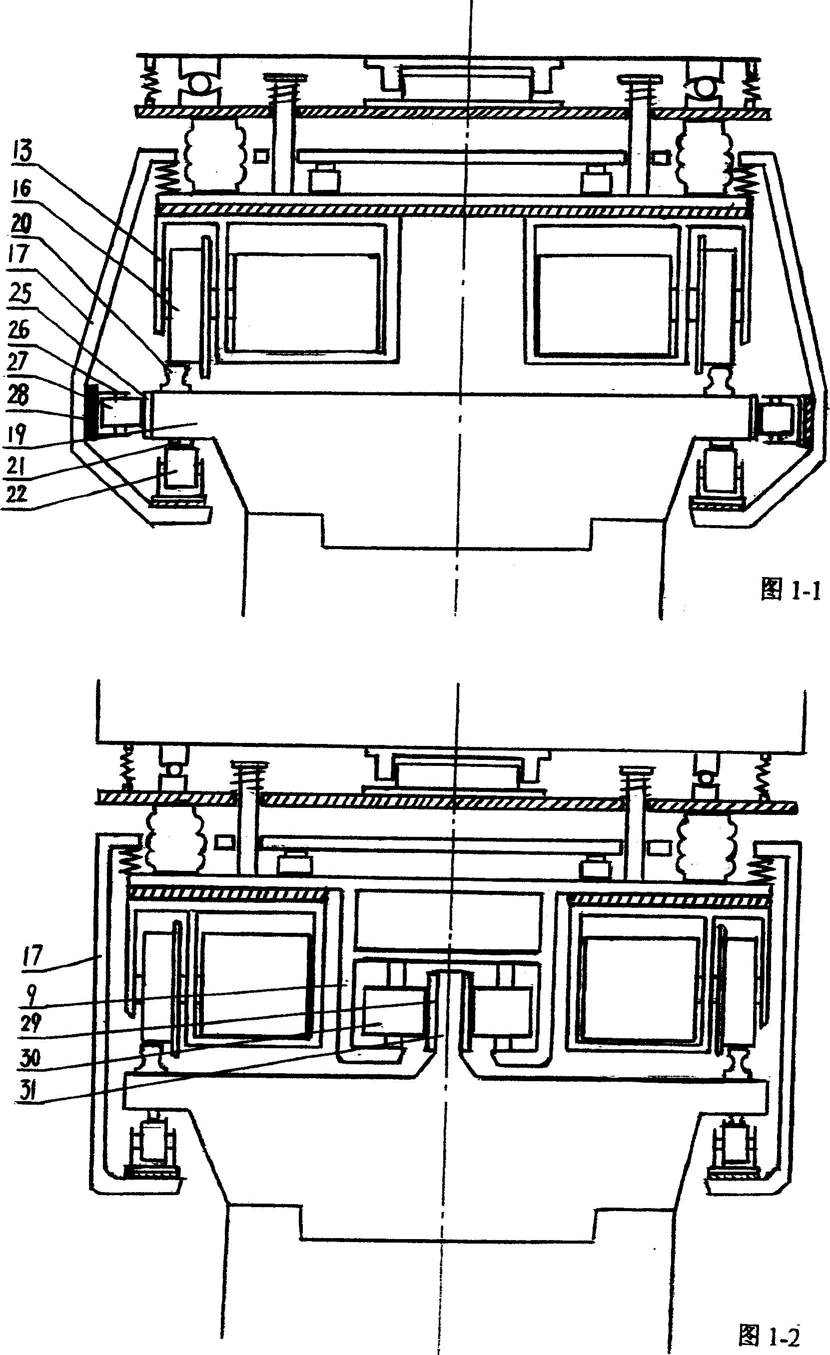
[0026] Referring to Fig. 1 and Fig. 1-3, the rotating shaft 3 provided on the lower support plate 4 of the compartment 1 is inserted into the shaft hole 2 installed at the bottom of the compartment, and a shaft disc 5 and a tension spring are installed between the support plate 4 and the bottom of the compartment Hydraulic cylinder 7 and spring 11 are housed between the base plate 10 and the power supply guide frame 17 above it, the pressure in the hydraulic cylinder 7 is provided and controlled by the hydraulic device in the car, and the air spring 8 passes through the opening on the power supply guide frame 17 The hole is installed between the base plate 10 and the support plate 4; the upper end of the guide rod 6 fixed on the base plate 10 passes through the guide rod hole on the power supply guide frame 17 and the support plate 4, and the top of the guide rod 6 is provided with a round platform, and the round platform Spring is housed between and supporting plate, and the e...

Embodiment 2

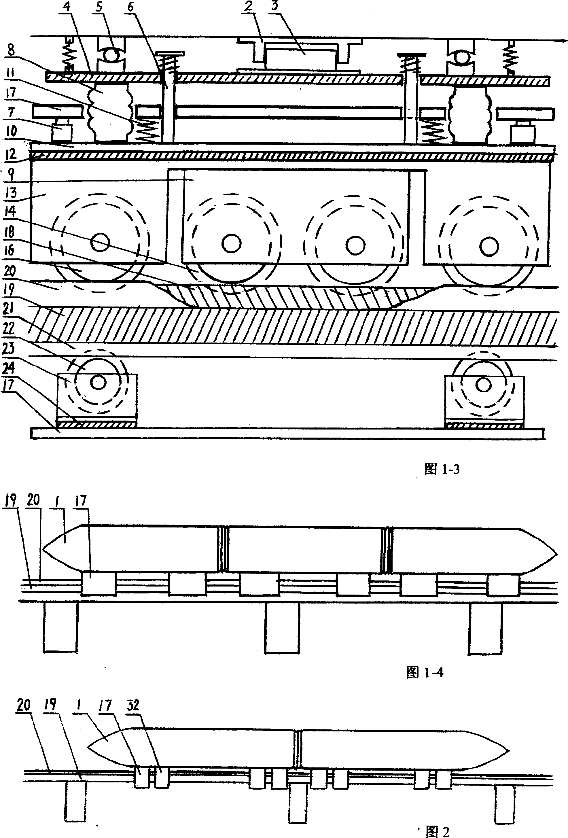
[0031] Referring to Figure 2 and Figure 2-1, the vehicle is powered by the conductive wheel 22 pressed against the conductive rail 21 in the power supply guide frame 17 under the carriage, driven by the drive wheel 16 in the drive wheel frame 13 under the carriage, and runs on the track On the rail 20 on the beam 19, the compartment 1 is suspended on the track beam by the suspension suction generated between the suspension guide electromagnet 42 provided at the lower end of the suspension guide frame 32 below it and the suspension support rail 39 provided below the two sides of the track beam. , so that the weight of the car itself is directly transferred to the track beam through the suspension support rail 39, eliminating the car load borne by the driving wheel 16 and the driving wheel frame 13, so that the driving wheel 16 only needs to drive the following parts of the car with the driving wheel frame 13 load At the same time, it drives the carriage suspended above it that d...

Embodiment 3

[0037] Referring to Fig. 4, a power supply guide frame 17, a support plate 4 and a base plate 10 are arranged below the compartment 1, and the relationship between the compartment and the three is the same as that described in Embodiment 1, and the two outer sides of the power supply guide frame 17 are installed respectively. There are conductive wheels 22 and guide wheels 27; side beams 46 are arranged above the two sides of the rail beam 19, and conductive rails 21 and guide rails 25 are respectively arranged in the side beams 46, and the conductive wheels 22 on the power supply guide frame 17 are powered The spring 11 installed on the bottom plate below the guide frame or the effect of the hydraulic cylinder 7 press on the conductor rail 21, and the guide wheel 27 is also positioned at one side of the guide rail 25 simultaneously. When the vehicle is running at a high speed, the spring 11 and the hydraulic cylinder 7 press the conductive wheels on both sides of the power sup...


PUM


Abstract

The present invention relates to a high-speed track traffic vehicle, mainly formed from high-speed track vehicle and track beam. It is characterized by that when the vehicle is running on the overhead track beam at high speed, the drive friction pressure required for all the drive wheels in the vehicle can be provided by springs placed in the vehicle and rolling device capable of regulating pressure, and the electromagnetic suspended electromagnetic iron placed in the vehicle and suspended supporting track on the track beam are interacted between them, so that the carriage can be suspended on the track beam, and can be driven by the driving wheel in vehicle and can be run at high-speed.

Description

technical field [0001] The invention relates to a high-speed rail vehicle, in particular to a high-speed rail vehicle with adjustable ground pressure by using its own hydraulic device to increase and adjust the frictional pressure between the wheels and rails of the high-speed rail vehicle. Background technique [0002] The friction pressure (adhesion force) between the wheels and the rails of the current high-speed rail vehicles mainly depends on the self-weight of the traction locomotive. As the speed of the train increases, the friction pressure between the wheels and the rails also decreases, causing the speed to be affected. However, the driving safety of the vehicle is greatly affected due to the reduction of the friction pressure. Although the friction pressure between the wheel and the rail in the "Intercity High-speed Light Rail Transit" with the application number 01141380.8 has been greatly improved, However, because the setting of the door frame and the top rail ...

Claims


Application Information

Patent Timeline
Patent Type & Authority Patents(China)
IPC IPC(8): B61B13/08B61D15/00
Inventor 李孝龙
Owner 李孝龙
Why Eureka
Try Eureka