
Stator structure for reciprocating motor

A technology of stator structure and reciprocating motion, applied in the field of mechanical engineering, can solve the problems of general products without structure, and achieve the effects of reducing manufacturing costs, preventing channel blockage, and preventing abnormal compounds

Inactive Publication Date: 2007-07-18
LG ELECTRONICS (TIANJIN) APPLIANCES CO LTD
View PDF2 Cites 0 Cited by
  • Summary
  • Abstract
  • Description
  • Claims
  • Application Information

AI Technical Summary

Problems solved by technology

[0019] In order to solve the above-mentioned problems of the stator structure of the reciprocating motor, the relevant manufacturers have tried their best to find a solution, but no suitable design has been developed for a long time, and there is no suitable structure for general products. The above-mentioned problems are obviously the problems that relevant industry players are eager to solve

Method used


Image

  • Stator structure for reciprocating motor
  • Stator structure for reciprocating motor
  • Stator structure for reciprocating motor

Examples


Embodiment Construction

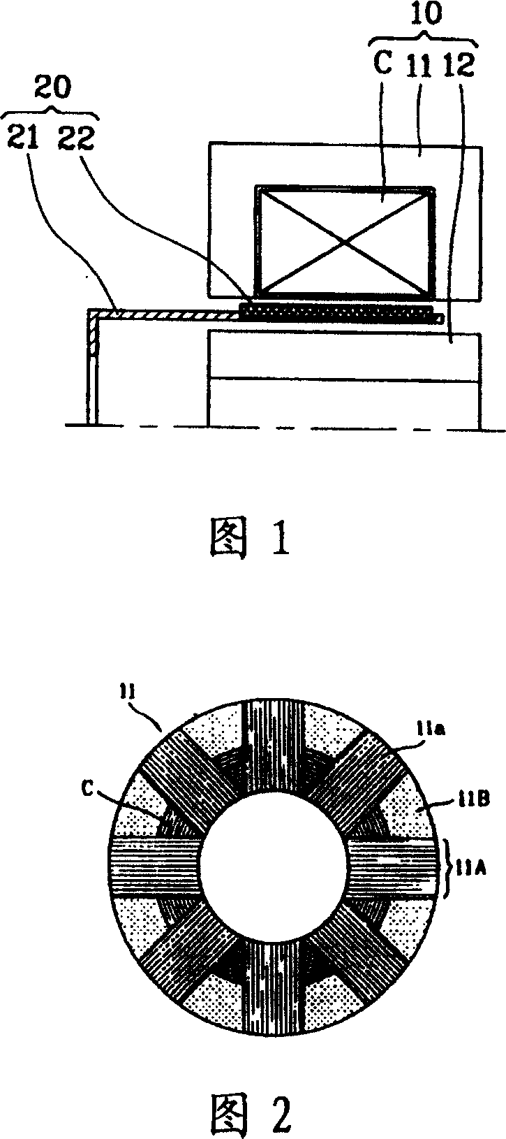
[0046] The specific implementation, structure, features and functions of the stator structure of the reciprocating motor according to the present invention will be described in detail below with reference to the accompanying drawings and preferred embodiments.

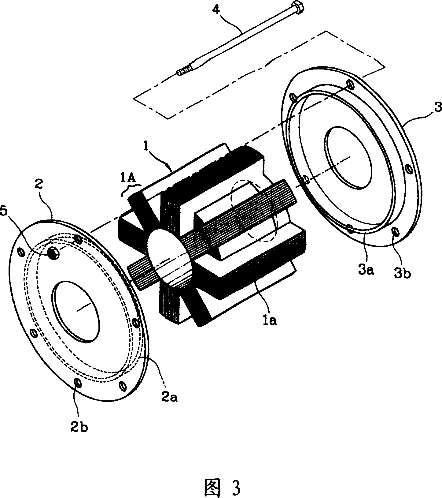
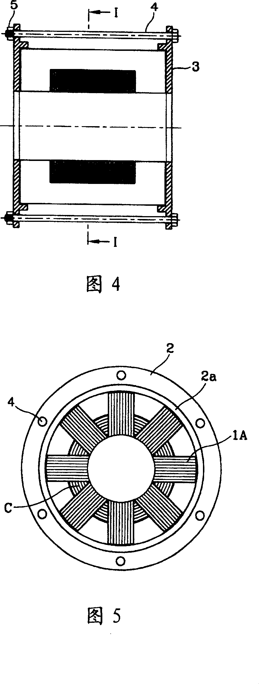
[0047] Please refer to Fig. 3, Fig. 4, shown in Fig. 5, Fig. 3 is the schematic diagram of the outer stator on the reciprocating motor of the present invention, Fig. 4 is the sectional view of the outer stator on the reciprocating motor of the present invention, shown in Fig. 5 It is a sectional view along line "I-I" in Fig. 4 .

[0048] Please refer to shown in Fig. 3, according to the outer stator of the reciprocating motor proposed by the present invention, it comprises: several stator iron cores 1a layer upon layer put into the stator core group 1A of substantially regular hexahedron shape, this stator core group 1A A laminated body 1 stacked radially in a cylindrical shape, several plates 2, 3 supporting it on both ...


PUM


Abstract

Stator structure comprises the stator iron core groups, the radial shaped laminated bodies, the plate bodies, and fastener. Several pieces of thin stator iron core are piled as a stator iron group. These piecemeal groups are built up in radial shape so as to form a laminated body. The plate bodies are on two sides of laminated body to support and fit with the laminated body closely. The fastener of plate body keeps shape of the laminated body unchanged. The invented structure retains original shape of the stator, and reduces manufacturing cost. Side effect of thermal deformation is reduced so as to raise efficiency and reliability of motor. The invention also prevents generating of abnormal compound as well as blockage of channels.

Description

technical field [0001] The invention relates to a motor in the field of mechanical engineering, in particular to a stator structure of a reciprocating motor. Specifically, it relates to a stator structure of a reciprocating motor capable of lowering the assembly cost and easier operation of the outer stator and preventing distortion caused by thermal deformation after assembly. Background technique [0002] In general, a reciprocating motor is formed by deforming the magnetic field of a three-dimensional motor into a planar shape. In other words, a flat-plate-shaped rotor is placed above a flat-plate-shaped stator, and it moves linearly according to changes in the magnetic field. [0003] The movement principle of the recently introduced reciprocating motor is as follows: the stator is set as a cylindrical outer stator and an inner stator with a certain interval between them, the rotor moves between the outer stator and the inner stator, and the outer stator moves between t...

Claims


Application Information

Patent Timeline
IPC IPC(8): H02K1/12H02K33/00
Inventor 韩必莞
Owner LG ELECTRONICS (TIANJIN) APPLIANCES CO LTD
Learn More