System and method for steam turbine backpressure control using dynamic pressure sensors

A technology of steam turbine and control system, which is applied in the direction of steam engine device, engine components, starting of engine, etc.

Inactive Publication Date: 2007-08-01
GENERAL ELECTRIC CO
View PDF7 Cites 0 Cited by
  • Summary
  • Abstract
  • Description
  • Claims
  • Application Information

AI Technical Summary

Problems solved by technology

The disadvantage of this control system is that the setpoints for alarm and disconnection are based on static pressure values ​​only, and thus tend to be conservative

Method used


Image

  • System and method for steam turbine backpressure control using dynamic pressure sensors
  • System and method for steam turbine backpressure control using dynamic pressure sensors
  • System and method for steam turbine backpressure control using dynamic pressure sensors

Examples


Embodiment Construction

[0020] The following detailed description uses examples to explain the present invention, but these examples do not limit the present invention. This description clearly enables one skilled in the art to make and use the invention, and it describes several embodiments of the invention, several improvements, variations, substitutions and uses, including the invention of the best mode for carrying out the invention.

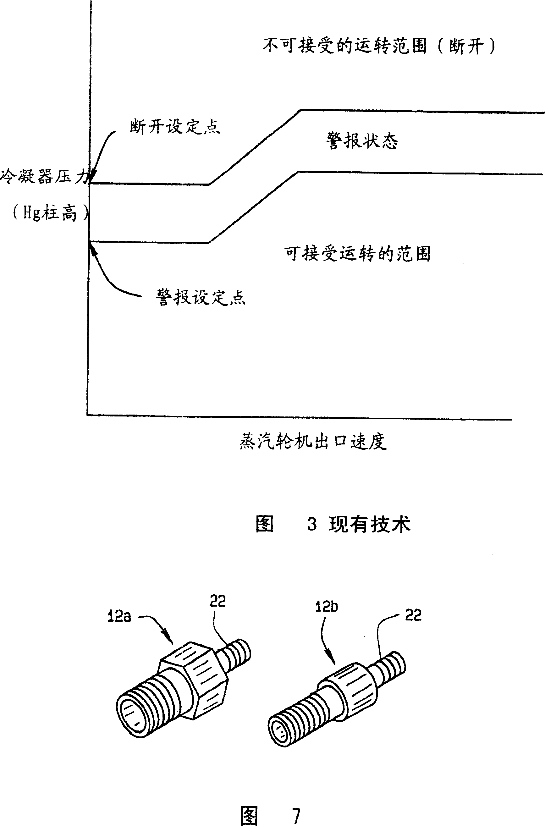
[0021] According to the present invention and as shown in FIG. 4 , the steam turbine control system of the present invention is indicated by reference numeral 10 . According to the invention, one or more dynamic pressure sensors or probes 12 are positioned around the periphery of the blades B comprising the last stage Sn of the turbine T. Such as indicated at 12a and 12b of Figure 7, the sensor detects the pressure value or magnitude in this region of the turbine during operation of the turbine. Because the sensors are dynamic pressure sensors, they detect instabi...


PUM


Abstract

A system (10) controlling operation of a steam turbine (T). Sensors (12) measure dynamic pressure level variations in a stage (S1-Sn) of the turbine. A signal (Ps) from a sensor is converted to a frequency based signal (Fs). A comparator (16) compares the pressure levels at various frequencies as represented by the frequency based signal (Fs) to a matrix of limiting values including both alarm and trip signal limits. The control system provides an alarm to an operator of the steam turbine if the comparison indicates that an alarm limit has been exceeded, or takes the steam turbine off line, if a trip signal limit has been exceeded. This is done to prevent damage to the steam turbine. However, the control system maintains the steam turbine in operation if no aeromechanical disturbances or instabilities, as sensed by the sensors, has occurred.

Description

technical field [0001] The present invention relates to a control system and method for informing a steam turbine of operating flexibility to accommodate changes in ambient temperature and / or condenser cooling capacity. These changes affect the steam turbine by changing the exhaust pressure or back pressure of the system. Background technique [0002] A steam turbine receives high-pressure, high-temperature steam that expands through stationary and moving rows of nozzles and blades ("turbine blades") to convert thermal energy into mechanical (rotary) energy. Combining a steam turbine with a generator produces electricity. Figure 1 shows a representative steam turbine power plant. As shown in FIG. 1, a steam turbine T drives a generator G by rotation of a rotor R on which blades or turbine blades B are mounted. A turbine generally consists of a series of stages S1-Sn, where stage Sn is the last stage of the turbine. Steam flows to the turbine through a control valve V, an...

Claims


Application Information

Patent Timeline
Patent Type & Authority Patents(China)
IPC IPC(8): G01M15/00G01M19/00F01K7/14F01K7/16F01D19/00F01D21/00F01D21/16G01M99/00
CPCF01K7/165
Inventor C·L·范德沃尔特
Owner GENERAL ELECTRIC CO
Why Eureka
Try Eureka