Liquid crystal display unit

A liquid crystal display device and liquid crystal technology, applied in optics, instruments, nonlinear optics, etc., can solve the problems of brightness change, poor viewing angle relationship, large backward scattering of incident light, etc., and achieve the effect of color display

Inactive Publication Date: 2002-03-20
CITIZEN WATCH CO LTD
View PDF0 Cites 8 Cited by
  • Summary
  • Abstract
  • Description
  • Claims
  • Application Information

AI Technical Summary

Problems solved by technology

However, since the degree of scattering in the incident direction is high, the incident light is scattered backwards and the contrast decreases.
Furthermore, since the angular relationship with respect to the scattering of incident light is strong, the brightness will change rapidly, and the viewing angle relationship is very bad.

Method used


Image

  • Liquid crystal display unit
  • Liquid crystal display unit
  • Liquid crystal display unit

Examples


Embodiment 1

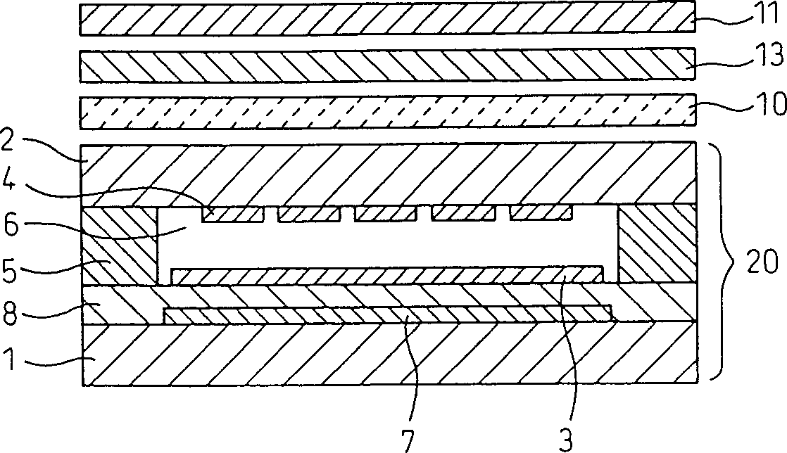
[0069] Figure 7 The configuration of the liquid crystal display device of Example 1 is shown. like Figure 7 As shown, the liquid crystal display device is equipped with a liquid crystal element 20, which is arranged on the upper side of the liquid crystal element 20, that is, an anisotropic scattering layer 10 arranged on the observer side through a reflector, a twisted retardation plate 12, and a first retardation plate 13. , the second phase difference plate 14 and the upper polarizer 11. In this embodiment, three phase difference plates, namely the twisted phase difference plate 12 , the first phase difference plate 13 and the second phase difference plate 14 are used as optical compensation elements.

[0070] The upper polarizer 11, the second retardation plate 14, the first retardation plate 13, the twisted retardation plate 12 and the anisotropic scattering layer 10 are bonded together with an acrylic adhesive. The liquid crystal element 20 and the anisotropic scatt...

Embodiment 2

[0105] Next, we describe embodiments of the liquid crystal display device of the present invention. The structure of the liquid crystal display device of embodiment 2 and figure 1 The configuration shown is the same. like figure 1 As shown, the liquid crystal display device is equipped with a liquid crystal element 20, an anisotropic scattering layer 10 provided on the viewer side through a reflector, a phase difference plate 13 as an optical compensation element, and an upper polarizer 11. The upper polarizer 11, the retardation plate 13 and the anisotropic scattering layer 10 are bonded together with an acrylic adhesive, and the liquid crystal element 20 and the anisotropic scattering layer 10 are also bonded together with an acrylic resin.

[0106] In addition, the configuration of the pixel portion of the liquid crystal display device is the same as Figure 8 Same as shown.

[0107] Since the configuration of the liquid crystal element 20 is the same as that used in Em...

Embodiment 3

[0128] We now describe Embodiment 3 of the present invention. The structure of the liquid crystal display device of this embodiment and figure 1 The composition shown is the same, and the composition of the pixel part is the same as Figure 8 Same as shown. Also, the configuration relationship of each component is also related to Figure 9 , the same as shown in 13.

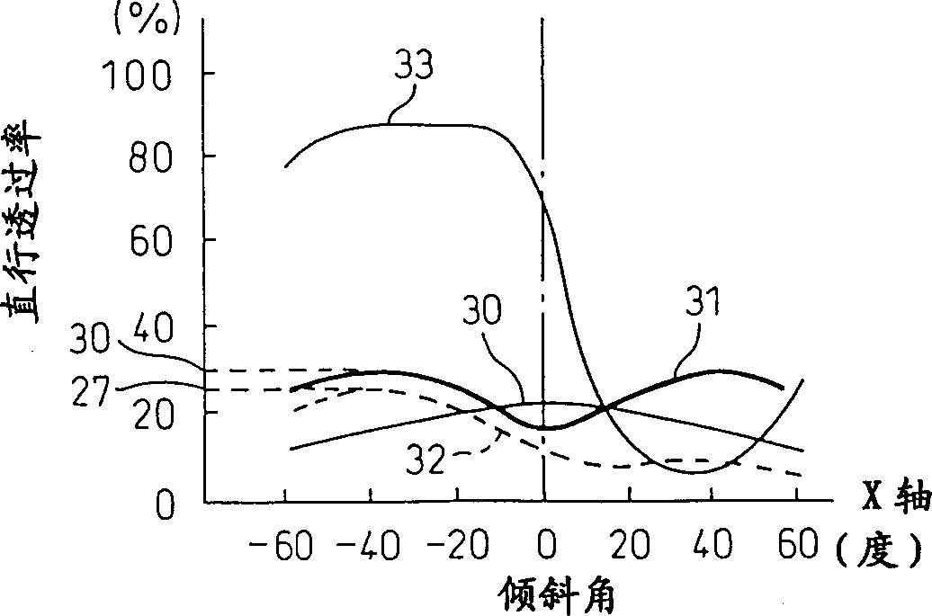
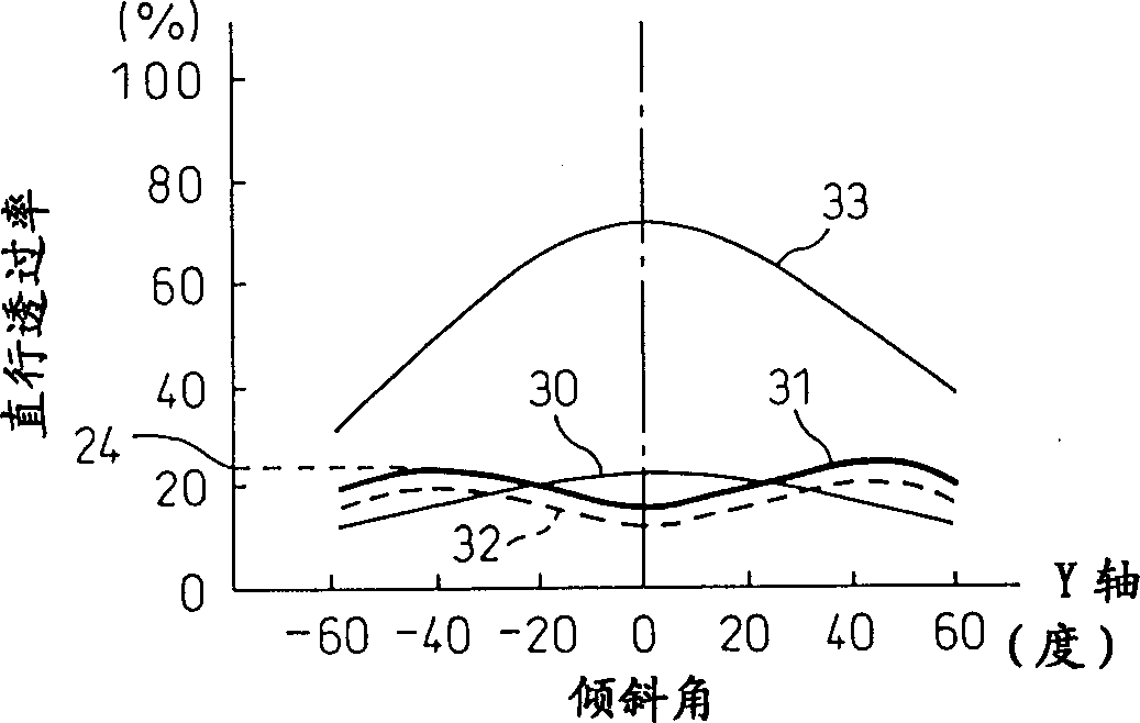
[0129] However, the liquid crystal display device of this embodiment uses Figure 5 and Image 6 The incidence angle dependence characteristic of an anisotropic scattering layer shown in curve 34 as figure 1 Anisotropic scattering layer 10.

[0130] The anisotropic scattering layer used in this embodiment, such as Figure 5 , as shown by the curve 34 in 6, the incident angle relationship characteristics in the X-axis direction and the Y-axis direction are the same, and the layer normal direction is symmetrical in both the X-axis direction and the Y-axis direction. The anisotropic scattering layer 10 with ...


PUM

PropertyMeasurementUnit
angleaaaaaaaaaa
thicknessaaaaaaaaaa
thicknessaaaaaaaaaa

Abstract

A liquid crystal display comprises a top polarizer 11, an optical compensating element, an anisotropic scattering layer 10, a scattering layer 9, and a liquid crystal device 20. When the direction of viewing direction of the anisotropic scattering layer is designated as the Y-axis direction, and a direction oriented substantially at right angles to the Y-axis direction is designated as the X-axis direction, light entering the anisotropic scattering layer is scattered over a wider angle along the Y-axis direction than along the X-axis direction. Further, the incident angle dependence of the straight-go transmittance of the anisotropic scattering layer is symmetrical about the layer normal, and the straight-go transmittance in the layer normal direction is lower than the straight-go transmittance in any oblique direction.

Description

technical field [0001] The present invention relates to the structure of a liquid crystal display device, in particular to a reflective liquid crystal display device in the form of a single polarizer for bright black-and-white display and color display, which is composed of a reflector inside the liquid crystal display element and a polarizer. Background technique [0002] In the past, reflective liquid crystal display devices mainly used a pair of polarizers, and between the reflective layers arranged outside one of the polarizers, TN (twisted nematic) liquid crystal elements and STN (super twisted nematic) ) A reflective liquid crystal display device of a liquid crystal element. However, in this method, brightness is low, and furthermore, since the reflective layer is outside the glass substrate, there are problems in that shadows are generated in the display. [0003] As a countermeasure against the above-mentioned problems, a reflection type liquid crystal display dev...

Claims


Application Information

Patent Timeline
Patent Type & Authority Applications(China)
IPC IPC(8): G02F1/1335G02F1/13363
CPCG02F1/133504G02F1/133555G02F1/13363G02F2203/02G02B5/0236G02B5/0257G02F1/1335
Inventor 金子靖新井真
Owner CITIZEN WATCH CO LTD
Why Eureka
Try Eureka