Low temp air separation system adopting integrated pressurizing compression and multiple group sub-refrigerating compression

A low-temperature air separation, booster compressor technology, applied to the compression of fluids. field, which can solve the problems of expensive compressor installation, maintenance and operation

Inactive Publication Date: 2002-04-10
PRAXAIR TECH INC
View PDF0 Cites 9 Cited by
  • Summary
  • Abstract
  • Description
  • Claims
  • Application Information

AI Technical Summary

Problems solved by technology

Since compressors are relatively expensive to install, maintain and operate, any improvement in th

Method used


Image

  • Low temp air separation system adopting integrated pressurizing compression and multiple group sub-refrigerating compression
  • Low temp air separation system adopting integrated pressurizing compression and multiple group sub-refrigerating compression
  • Low temp air separation system adopting integrated pressurizing compression and multiple group sub-refrigerating compression

Examples


Example Embodiment

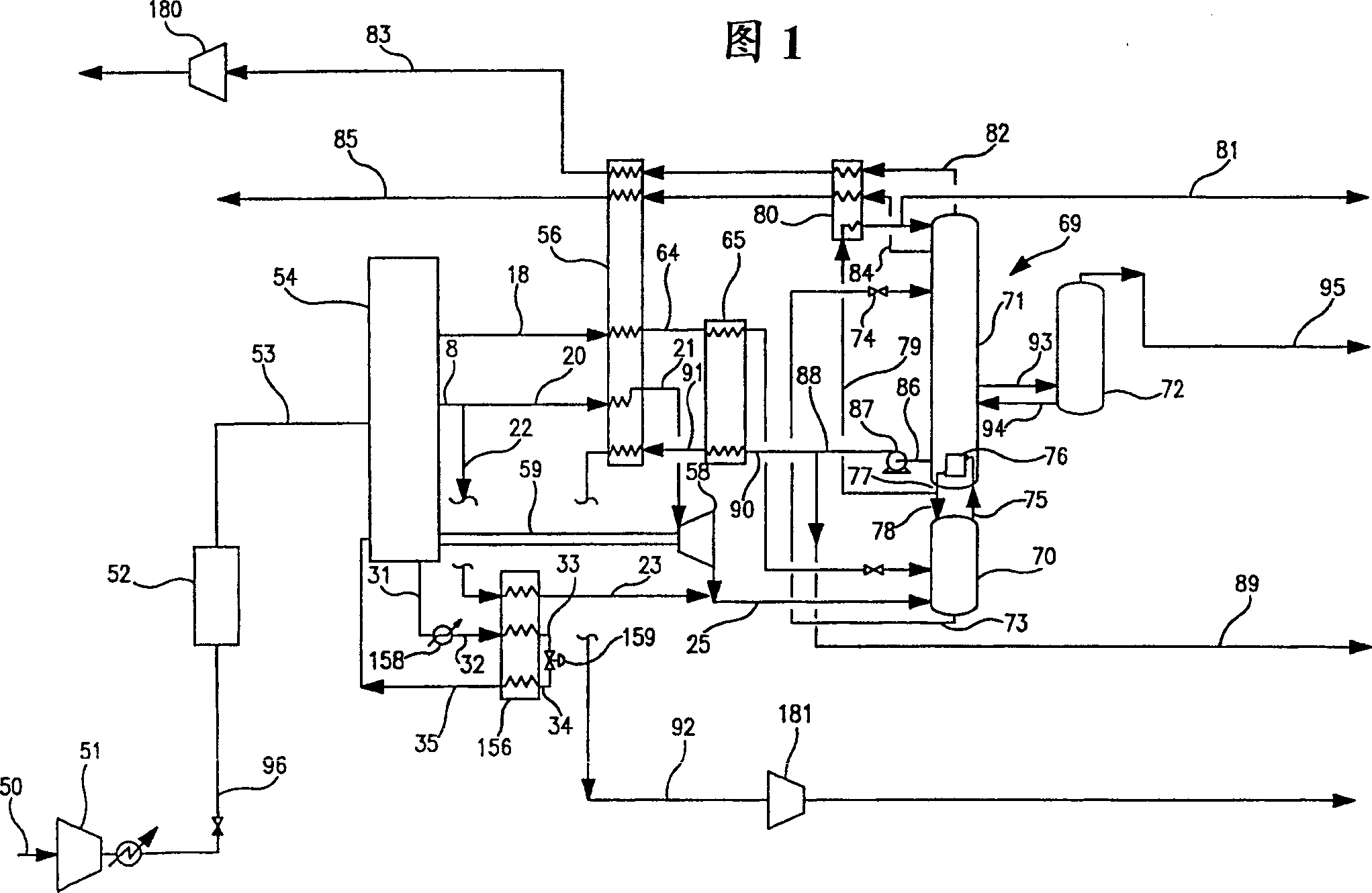
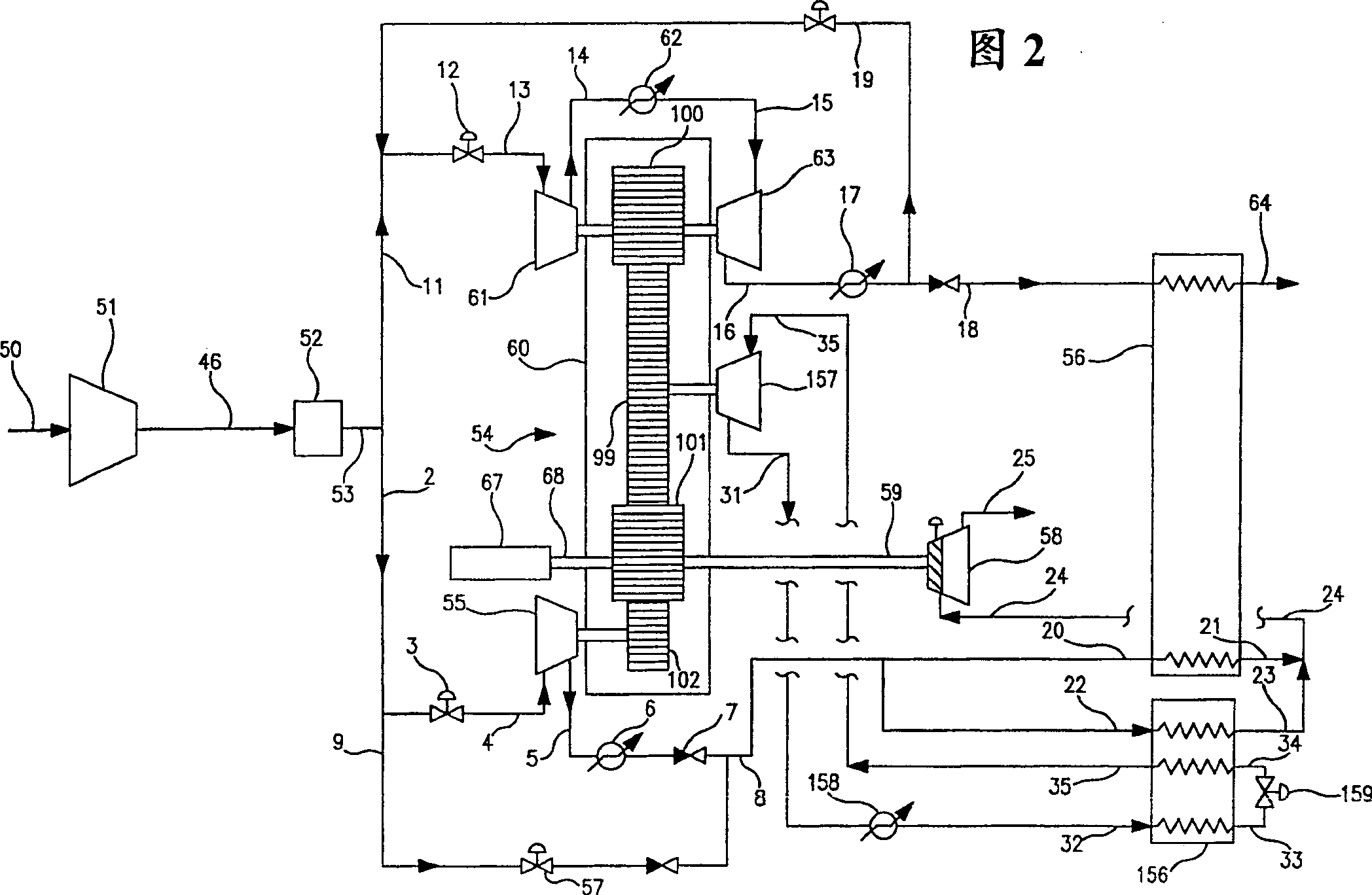
[0043] The present invention will be described in detail with reference to the accompanying drawings. 1 and 2, the feed air represented by the feed air stream 50 supplied to the cryogenic air separation plant is sent to the base load air compressor 51, where the air stream is compressed into a base load pressure (absolute pressure The range is usually 80-110 pounds per square inch (psia)). The base load pressure provides sufficient energy to the cryogenic air separation equipment to separate the feed air into one or more of product oxygen, product nitrogen, and product argon to obtain a gaseous product with a nominal pressure and a liquid product with a nominal quantity (usually About 2% of the feed air). Then the feed air 96 at the base load pressure is passed through the pre-purifier 52 to remove various high-boiling impurities (such as water vapor, carbon dioxide and hydrocarbons), and then the clean feed air 53 at the base load pressure is provided to the bridge machine. 54 (r...


PUM


Abstract

A cryogenic air separation system wherein pressure energy is supplied by a bridge machine having one or more booster compressors and a multicomponent refrigerant fluid compressor of a multicomponent refrigerant fluid circuit, all of the compressors of the bridge machine driven by power supplied through a single gear case.

Description

technical field [0001] The present invention relates generally to cryogenic air separation and, more particularly, to the compression of fluids in the operation of cryogenic air separation systems. Background technique [0002] A series of compressors are used in the operation of conventional cryogenic air separation systems. Some of these may be used to compress product, some to compress feed air, and others to run various internal circuits such as steam pumps or liquefier circuits. Since compressors are relatively expensive to install, maintain and operate, any improvement in the use of compression plants in conjunction with cryogenic air separation plants would be desirable. [0003] Accordingly, one of the objects of the present invention is to provide a cryogenic air separation system with an improved compression arrangement. Contents of the invention [0004] The above and other objects which will become apparent to those skilled in the art upon reading this disclo...

Claims


Application Information

Patent Timeline
IPC IPC(8): F25J3/04
CPCF25J3/04381F25J3/04218F25J3/04139F25J3/04412F25J2230/20F25J3/04145F25J3/04024F25J3/04672F25J2245/40F25J2240/30F25J3/04296F25J2270/12F25J3/04781F25J3/04278F25J2270/66F25J3/04175F25J3/04
Inventor K·W·马霍尼D·P·博纳奎斯特
Owner PRAXAIR TECH INC
Why Eureka
Try Eureka