Solar cell assembly and electric generating device

A technology of solar cells and devices, applied in battery circuit devices, circuit devices, energy conversion devices, etc.

Inactive Publication Date: 2002-05-01
CANON KK
View PDF1 Cites 10 Cited by
  • Summary
  • Abstract
  • Description
  • Claims
  • Application Information

AI Technical Summary

Problems solved by technology

[0005] The present invention has been proposed to solve each or all of the above problems, and the present invention aims to prevent overcurrent in solar cell modules

Method used


Image

  • Solar cell assembly and electric generating device
  • Solar cell assembly and electric generating device
  • Solar cell assembly and electric generating device

Examples


no. 1 example

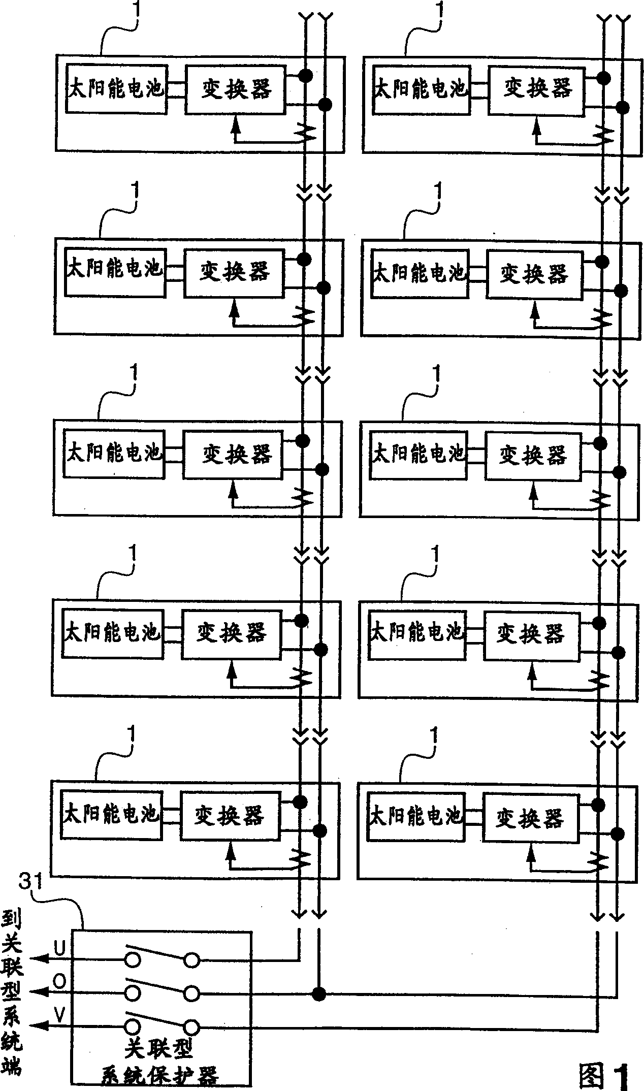
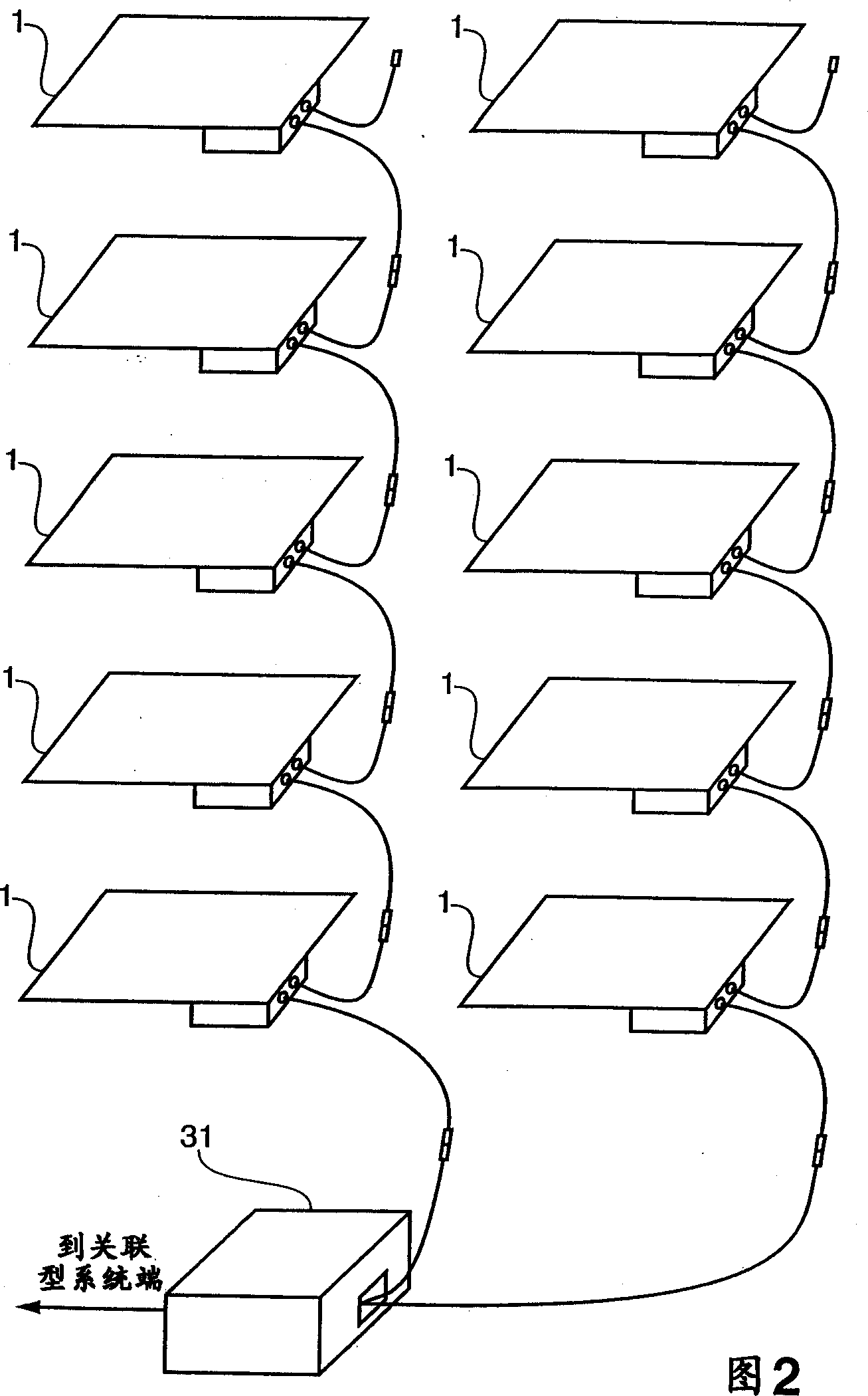
[0023] FIG. 1 is a block diagram explaining the structure of a photovoltaic power generation device using a plurality of AC modules; FIG. 2 is an external view of the photovoltaic power generation device.

[0024] The distribution line consists of two transmission lines U and V and a neutral line O. The U-phase and V-phase are AC 100V respectively, and these distribution lines constitute a 200V single-phase three-wire transmission line. Therefore, each AC component 1 has a single-phase output of 100V. As shown in Figures 1 and 2, the output connectors of the AC modules 1 are used to connect the input connectors, so that the number of parallel AC modules can be increased. 1 and 2 show an example in which five AC components 1 are connected to each of the U phase and the V phase (10 AC components 1 in total).

[0025] An associated system protector 31 including a switch and a system abnormality detector is provided between the AC component 1 and the industrial power system (her...

no. 2 example

[0050] A photovoltaic power generation device according to a second embodiment of the present invention will be described below. Note: In the second embodiment, the same configurations as those of the first embodiment are assigned the same reference numerals and their detailed descriptions are omitted.

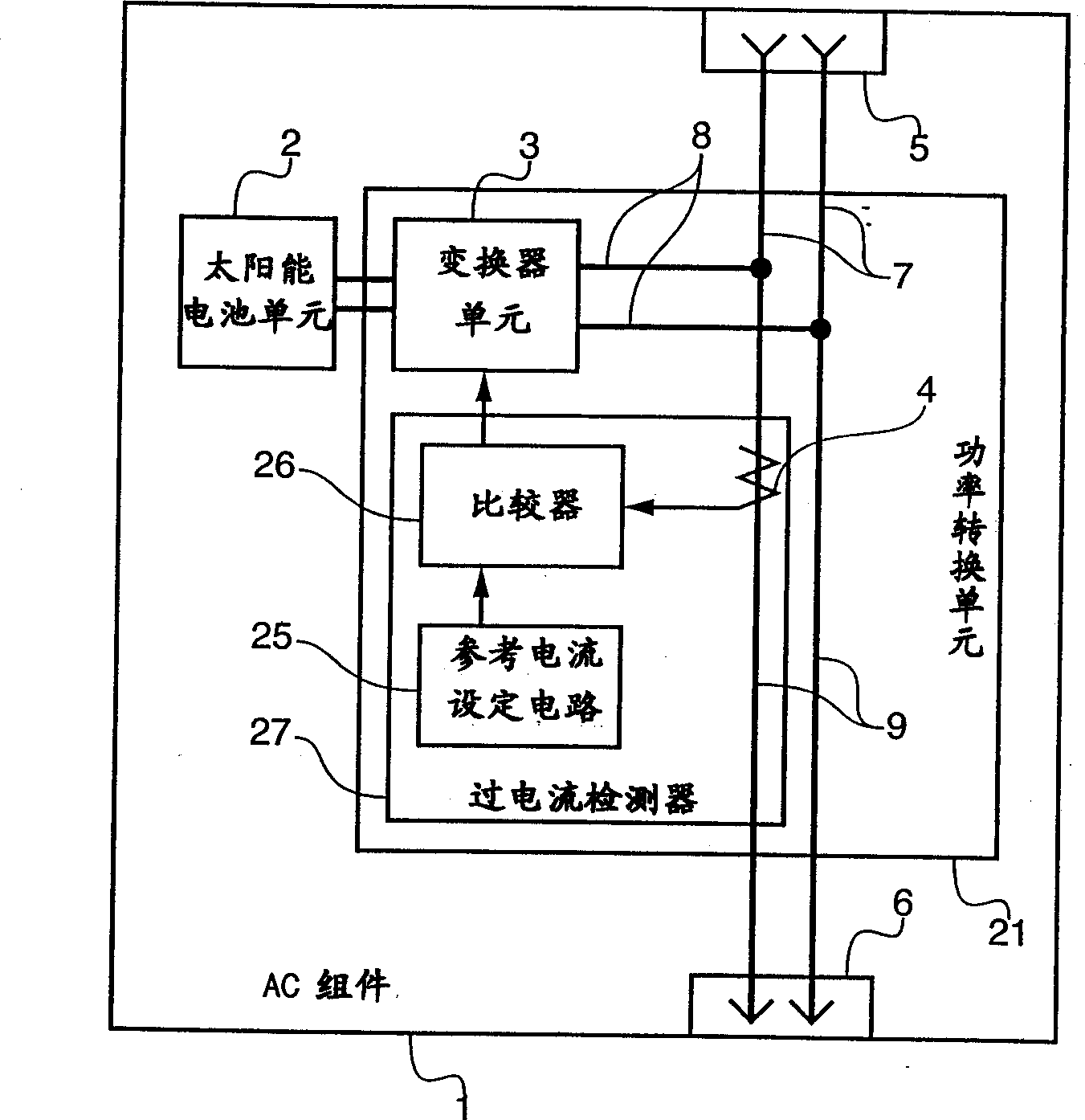
[0051] In the first embodiment, when the detection value of the current detector 4 exceeds the set value, the output of the AC component 1 is stopped. On the contrary, according to the second embodiment, the output of the AC component 1 is lowered so that the detection value of the current detector 4 does not exceed the set value.

[0052] Figure 7 is a block diagram showing the structure of the AC assembly 1 according to the second embodiment. Set subtractor 54 to replace image 3 The comparator 26 shown in the AC component 1 structure.

[0053] The subtractor 54 subtracts the set value of the reference current setting circuit 25 from the output value of the current detec...

no. 3 example

[0061] A photovoltaic power generation device according to a third embodiment of the present invention will be described below. Note: In the third embodiment, the same configurations as those of the first embodiment are assigned the same reference numerals and their detailed descriptions are omitted.

[0062] The first and second embodiments employ an AC assembly 1 coupled to a single-phase two-wire system line. The third embodiment employs an AC assembly 1 coupled to a single-phase three-wire system line.

[0063] Figure 9 is a block diagram showing the structure of the AC component 1 connected to the line of the single-phase three-wire system. although Figure 9 shows the structure of supplying power to the U-phase line, but it can also be supplied to Figure 10 The V-phase line shown is powered.

[0064] and image 3 with Figure 7 Unlike the AC assembly 1 shown in , the input connector 51 and the output connector 61 of the AC assembly 1 according to the third embodi...


PUM


Abstract

AC module, integrating a solar battery and an inverter, can easily be connected with other plural AC modules in parallel by way of cascade connections. However, when the number of AC modules connected is improvidently increased, the current flowing through the current path or connector of the AC module exceeds a rated current. In view of this, the current detector detects a current in the collective-power current path of the AC module, and when the detected current value exceeds a value set in the reference current setting circuit, the current detector stops the inverter.

Description

technical field [0001] The present invention relates to a solar cell module and a power generating device, and more particularly, to a solar cell module including a solar cell and an electronic power converter and a power generating device using the solar cell module. Background technique [0002] Photovoltaic power generation systems that have been widely used in recent years include associated systems and independent systems that supply power to loads. The associated system provides an industrial AC power system that converts the power generated by solar cells to DC through a converter. / AC conversion obtained. [0003] An AC module for outputting alternating current has been put into practical use in recent years, which integrates a solar cell and an inverter circuit. As a configuration of AC modules, Japanese Patent Application Laid-Open No. Hei 10-14111 proposes an AC module capable of increasing the number of AC modules connected in parallel by sequentially repeating ...

Claims


Application Information

Patent Timeline
Patent Type & Authority Applications(China)
IPC IPC(8): H01L31/04G05F1/67H01L27/142H01L31/00H02J3/38H02J7/00H02M7/48H02N6/00
CPCH01L31/0428Y10S136/293Y02E10/563H02J3/383H02J3/382H02S40/32H02J2300/24H02J3/381Y02E10/56H02J3/46
Inventor 近藤博志竹原信善黑神诚路
Owner CANON KK
Why Eureka
Try Eureka