
Fabric component detecting ultraviolet laser method

A UV laser and fabric technology, applied in the measurement of color/spectral properties, material inspection products, textile testing, etc., can solve problems such as inability to distinguish between chemical fiber fabrics and blended fabrics, damage to finished fabrics, and inability to judge the percentage of cotton and chemical fibers. To achieve the effect of accurate judgment and intuitive phenomenon

Inactive Publication Date: 2002-05-22
SHANGHAI INST OF OPTICS & FINE MECHANICS CHINESE ACAD OF SCI
View PDF0 Cites 1 Cited by
  • Summary
  • Abstract
  • Description
  • Claims
  • Application Information

AI Technical Summary

Problems solved by technology

This method is more intuitive, simple and easy to implement, but it is impossible to judge the percentage of cotton and chemical fiber, and it is also difficult to distinguish chemical fiber fabrics from blended fabrics, and it will also cause damage to the finished fabric.

Method used


Image

  • Fabric component detecting ultraviolet laser method
  • Fabric component detecting ultraviolet laser method
  • Fabric component detecting ultraviolet laser method

Examples


Embodiment Construction

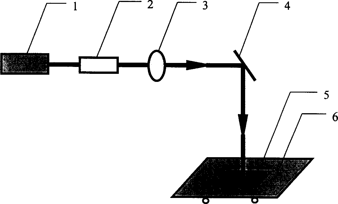
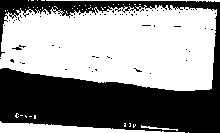
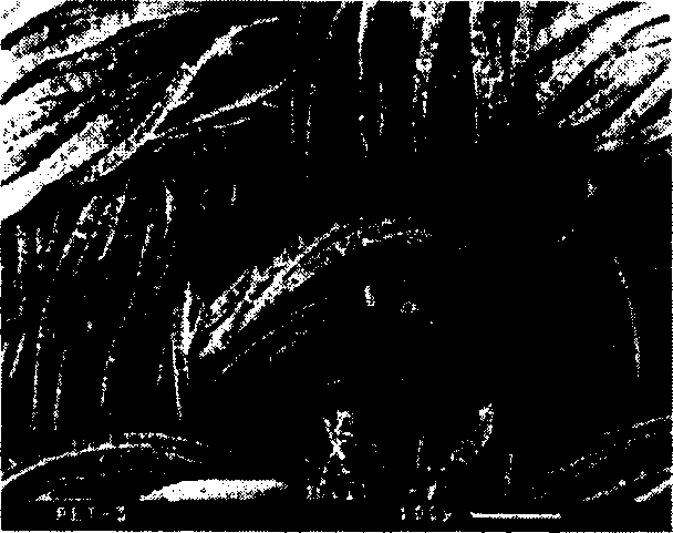
[0014] As above-mentioned method and specific steps of the present invention, the processing device of the ultraviolet laser that adopts is as figure 1 shown. The ultraviolet laser is an excimer laser 1, and the laser beam emitted by the excimer laser 1 passes through a tunable attenuator 2 and a lens 3 on the same horizontal axis as the excimer laser 1, and through a reflection placed at an angle of 45° to the horizontal line The mirror 4 irradiates onto the two-dimensional platform 5 placed horizontally directly under the mirror 4 , and the fabric 6 to be tested is placed flat on the platform 5 . The laser energy output by the excimer laser 1 is controlled by the tunable attenuator 2 , focused by the lens 3 , and then reflected by the mirror 4 to the surface of the fabric 6 to be tested placed on the two-dimensional platform 5 . After the fabric to be tested is treated, it is observed and photographed under an electron microscope, and a micrograph of the fabric to be teste...


PUM


Abstract

Said invention adopts UV laser beam whose power density is greater than melting threshold value of fabric surface to detected to irradiate the surface of fabric to be detected, then the treated fabric surface is placed under the microscope to make observation and obtain microphotograph of the detected fabric, then said obtained microphotograph is compared with the microphotograph of the sample toobtain the components of the detected fabric. As compared with existent technique its detection is accurate, and it does not damage the appearance of fabric.

Description

Technical field: [0001] The invention is a method for detecting fabric components with an ultraviolet laser, which is suitable for various chemical fibers, cotton, or blended fabrics. Background technique: [0002] When detecting the composition of a piece of fabric in the prior art, the method used is exactly to take out some samples, puts to burn under fire. The composition of the fabric can be judged by observing the shape of the residue after the fabric is burned. Become powdery carbon after the cotton fabric burns, and the chemical fiber fabric will solidify into a ball after burning (referring to prior art: " how to identify clothing material " written by the writing group of how to identify clothing material, published by Textile Industry Press, first edition in May, 1984 ). This method is more intuitive, simple and easy to implement, but it is impossible to judge the percentage of cotton and chemical fiber, and it is also difficult to distinguish chemical fiber fab...

Claims


Application Information

Patent Timeline
IPC IPC(8): G01N21/33G01N33/36
Inventor 楼祺洪周翔黄峰魏运荣董景星方爱平章琳
Owner SHANGHAI INST OF OPTICS & FINE MECHANICS CHINESE ACAD OF SCI
Learn More