Electric machine

A technology of rotors and force-applying components, which is applied in the field of motors and can solve problems such as poor position accuracy and deterioration of rotary position accuracy

Inactive Publication Date: 2002-06-12
NIDEC SANKYO CORP
View PDF0 Cites 1 Cited by
  • Summary
  • Abstract
  • Description
  • Claims
  • Application Information

AI Technical Summary

Problems solved by technology

As a result, the position accuracy of the bearing and the stator, which is also used as the thrust cover and serves as the position li

Method used


Image

  • Electric machine
  • Electric machine
  • Electric machine

Examples


Embodiment Construction

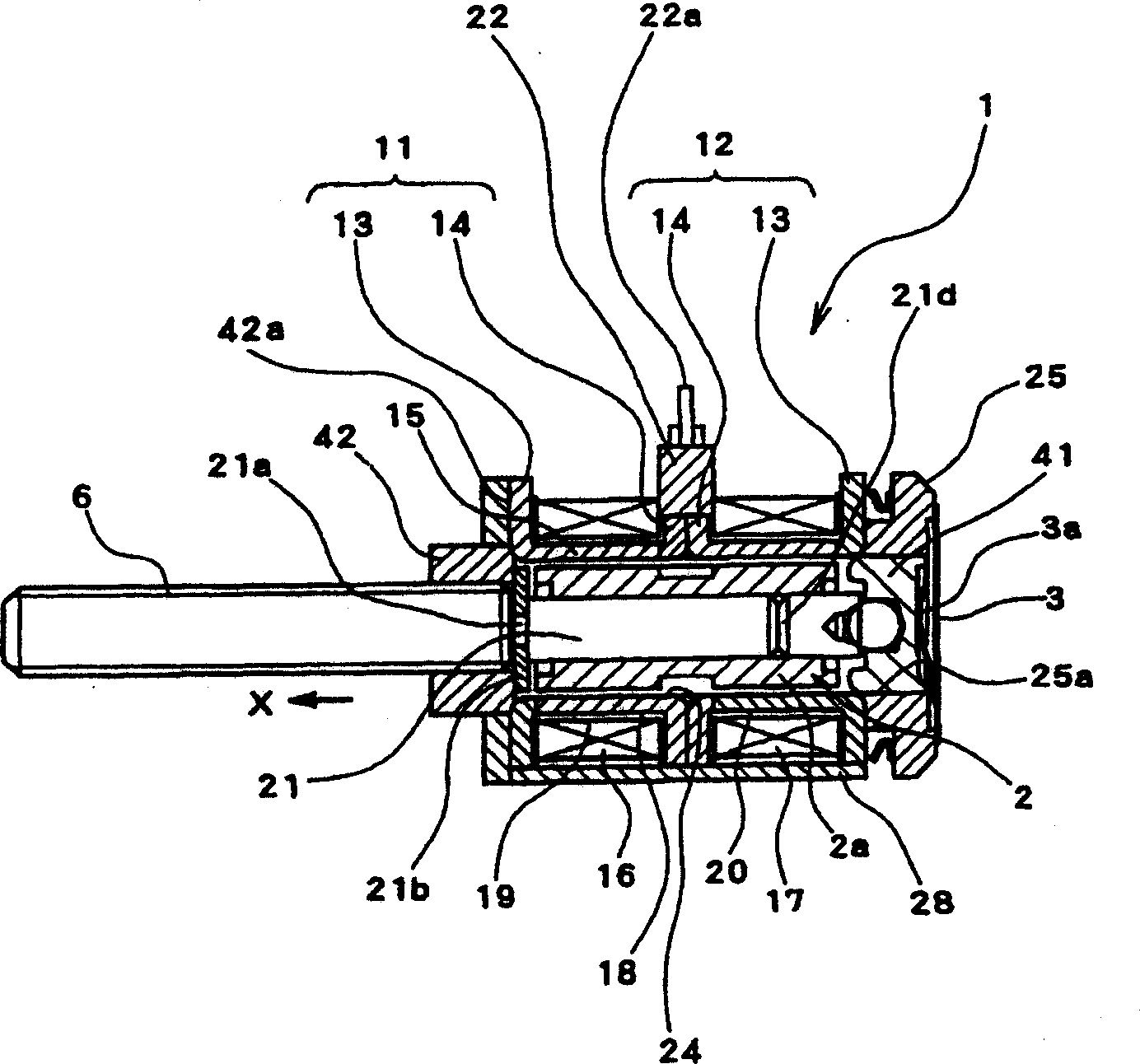
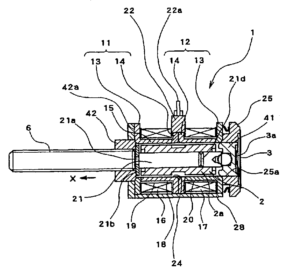
[0014] Embodiments of the present invention will be described below. figure 1 It is a sectional view showing the overall structure of the motor according to the embodiment of the present invention.

[0015] Such as figure 1 As shown, the motor of the embodiment of the present invention (this embodiment adopts the structure of a stepping motor, referred to as a motor for short here) has a stator 1 and a rotor 2 arranged opposite to the stator 1 . The rotor 2 is in the axial direction generated by the force member 3 described later (more specifically, figure 1 In the arrow X direction) to turn under the state of force. In addition, one end of the rotation center shaft 4 of the rotor 2 protrudes through a bearing 42 formed integrally with the stator 1 , and a threaded shaft portion 6 is formed at the penetrating portion and the protruding portion.

[0016] The stator 1 has a structure in which two sets of metal stator cores 11 and 12 are axially overlapped, and a rotatable ...


PUM


Abstract

The present invention provides a motor having an urging member for urging a rotor disposed oppositely to a stator in the axial direction, in which the rotor is rotated in a state under an urging force of the urging member, characterized in that a positional regulation part (bearing) for regulating the position of the rotor in a thrust direction under the urging force is integrally provided in a coil bobbin made of resin which has metallic stator cores making up the stator formed by insert molding. Therefore, the positional accuracy of the positional regulation part (bearing) with respect to the stator is made better. Thereby, the positional accuracy of the rotor with respect to the stator is also improved, so that the torque up is enabled.

Description

technical field [0001] The present invention relates to a motor that rotates a rotor while applying an axial force to the rotor. Background technique [0002] figure 2 Indicates that one side applies the axis direction to the rotation center axis ( figure 2 The traditional structure of the motor rotor part that rotates under the force of the arrow X1 direction in . The rotor 52 is rotatably supported by metal bearings (not shown) at two locations of the rotation center shaft 51 . One of the two metal bearings supporting the rotation center shaft 51 is attached to a fixed object such as a motor case. And, the bearing installed on the fixed object doubles as a thrust shield again, and is used to support one side of the rotor 52 that is biased in the axial direction. [0003] In addition, such a motor of rotating the rotor 52 while applying an axial force generally has a plurality of washers 53 including spring washers for pressing the rotor 52 against a bearing attached to...

Claims


Application Information

Patent Timeline
IPC IPC(8): H02K3/34H02K5/173H02K7/08H02K37/00H02K37/14H02K37/24
CPCH02K37/14H02K7/083H02K37/00
Inventor 矢岛克英务台仁志山本登子雄
Owner NIDEC SANKYO CORP
Why Eureka
Try Eureka