Glass Bodies And Methods Of Making

a glass body and glass body technology, applied in glass making apparatus, glass tempering apparatus, manufacturing tools, etc., can solve the problems of damage to the microlens and incur an additional manufacturing cost, and achieve the effect of reducing the cost of microlens manufacturing, enhancing/customizing the control of glass body shaping, and minimizing post processing shaping

Active Publication Date: 2010-05-13
CORNING INC
View PDF3 Cites 0 Cited by
  • Summary
  • Abstract
  • Description
  • Claims
  • Application Information

AI Technical Summary

Benefits of technology

[0008]Such glass bodies and / or methods of making the glass body, for example, a microlens address one or more of the above-mentioned disadvantages of conventional microlenses and / or methods of making microlenses and provide one or more of the following advantages: enhanced / customized control of shaping of the glass body, multiple potential applications for the glass bodies, reduced costs in microlens manufacturing since the need for post processing shaping is minimized, can provide different shaped microlenses on the same glass substrate at low cost, the microlenses and substrates can withstand high temperature applications, and / or customized arrays of microlenses can be made, for example, in lines or area shapes, evenly or unevenly distributed.

Problems solved by technology

This is due mainly to the mismatch of materials due to their coefficients of thermal expansion (CTE).
Materials such as plastic or polymer are typically used as substrates when glass based materials are not available or can not be used due to cost or processing reasons.
Alternatively, further processing steps at high temperatures of the substrate containing the microlens can damage the microlens.
Also several of the conventional methods require polishing of the microlenses prior to use, thus incurring an additional cost of manufacturing.

Method used


Image

  • Glass Bodies And Methods Of Making
  • Glass Bodies And Methods Of Making
  • Glass Bodies And Methods Of Making

Examples


examples

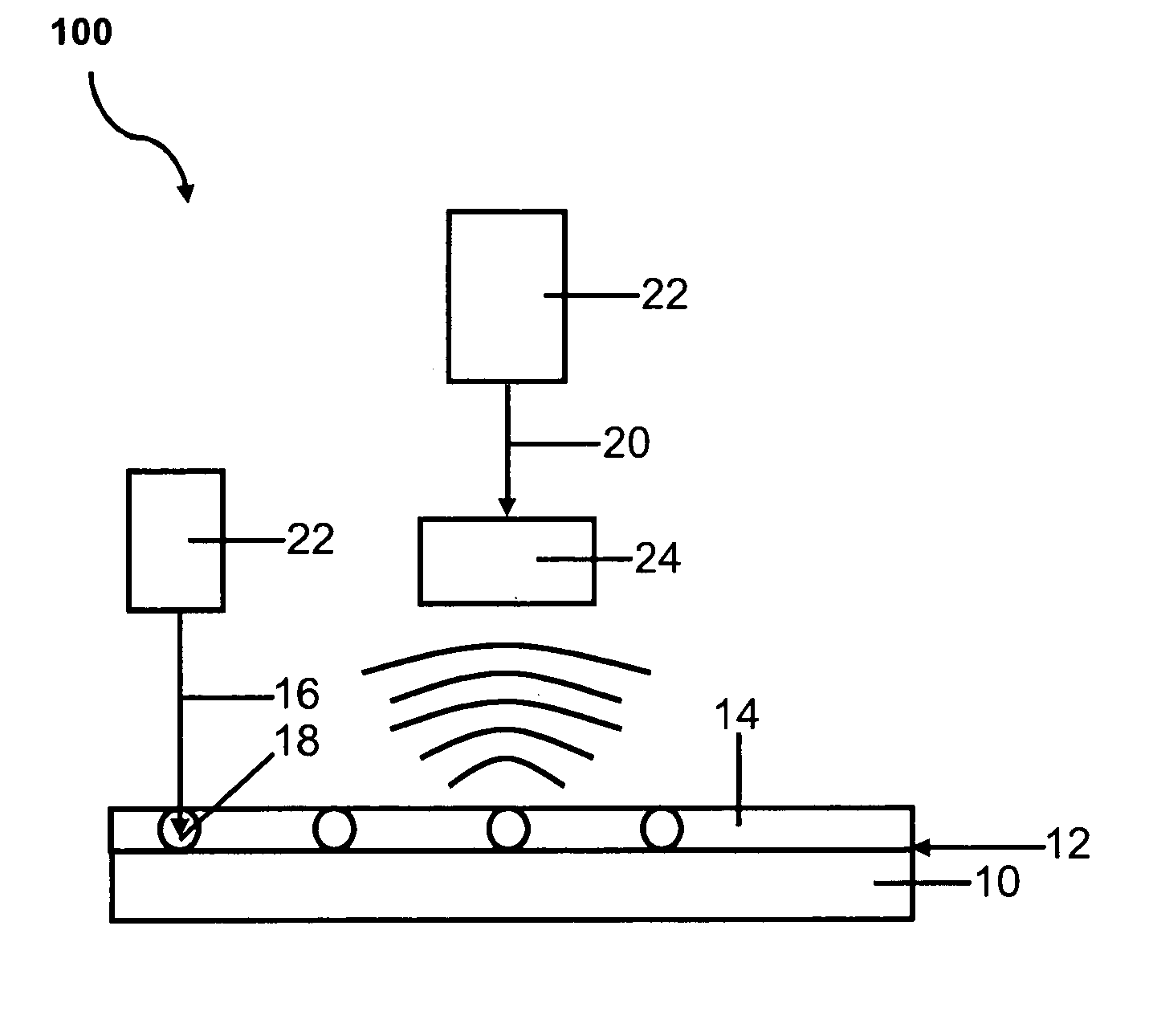
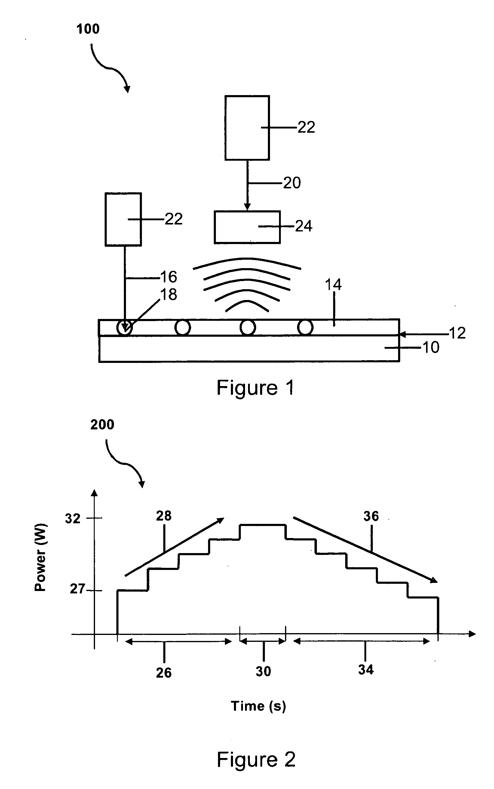
[0038]The following is an example of a method of making a glass body, according to one embodiment. A semiconductor laser array operating at 810 nm was connected to a fiber bundle as part of the INTEGRA laser system available from Coherent Inc. A lens arrangement was connected to the SubMiniature version A (SMA) connector of the laser with lenses with proper coating and optical focal lengths to provide a desired Gaussian beam shape or another beam shape of choice. The laser was incident on the cordierite powder that was disposed on the substrate. The cordierite powder was disposed in a layer having a uniform thickness. In this example, a mold was placed on a surface of the substrate. The mold was filled with cordierite powder and leveled using a putty knife. The substrate in this case was Corning 1737 glass, display glass, for example, Eagle 2000™ or soda-lime glass but other materials are also possible.

[0039]The cordierite powder used had particles with a distribution from 7 μm to 4...


PUM

PropertyMeasurementUnit
temperatureaaaaaaaaaa
diameteraaaaaaaaaa

Abstract

Glass bodies and methods of making glass bodies and more particularly glass bodies, for example, microlenses and arrays of microlenses and methods of making the same are described. Cordierite powder is vitrified to form a glass body or glass bodies for instance a microlens or microlenses.

Description

BACKGROUND[0001]1. Field[0002]Embodiments of the invention relate generally to glass bodies and methods of making glass bodies and more particularly to glass bodies, for example, microlenses and arrays of microlenses and methods of making the same.[0003]2. Technical Background[0004]Glass bodies, for example, microlenses are often used to couple light from a source to a detector (or user) and vice-versa. Many conventional microlenses are formed by cast molding of glass or plastic. Many conventional methods of making microlenses use lithographic patterning to define the general shape and size of the microlenses. Typically, the conventional methods either require the deposition or the removal of materials to define the shape after forming the microlens.[0005]Conventional deposition methods of making microlenses on substrates have some disadvantages. This is due mainly to the mismatch of materials due to their coefficients of thermal expansion (CTE). Materials such as plastic or polymer...

Claims


Application Information

Patent Timeline
Patent Type & Authority Applications(United States)
IPC IPC(8): C03C17/04C03C27/00
CPCC03B5/235C03B19/00C03B19/09C03C17/007C03C17/008C03C2217/28C03C2217/42C03C2218/13
Inventor SCHNEIDER, VITOR MARINOLAI, CHANGYI
Owner CORNING INC
Why Eureka
Try Eureka