Manifold incorporating thermoelectric module and cooling device using thermoelectric module

A modular and thermoelectric technology, applied in the field of manifolds, can solve the problems of difficult Peltier elements stacked into multiple layers, difficult positioning operations, difficult manufacturing, etc., to achieve miniaturization of the shape, reduction of the number of components, and heat exchange The effect of improving efficiency

Inactive Publication Date: 2005-02-02
MATSUSHITA REFRIGERATION
View PDF3 Cites 0 Cited by
  • Summary
  • Abstract
  • Description
  • Claims
  • Application Information

AI Technical Summary

Problems solved by technology

However, according to the structure disclosed by the prior art, there will be a problem of manufacturing difficulties
That is to say, the structure disclosed in the prior art is to arrange the Peltier element 200 and the electrode 202 in a circular shape, so positioning work and the like are difficult to perform.
[0017] In addition, Peltier elements can achieve lower temperatures by stacking them in multiple layers, but it is difficult to stack Peltier elements in multiple layers according to the conventional structure.
[0018] And, adopt the cooling device of thermoelectric module of prior art, then must be equipped with the pump that is used for circulating heat medium

Method used


Image

  • Manifold incorporating thermoelectric module and cooling device using thermoelectric module
  • Manifold incorporating thermoelectric module and cooling device using thermoelectric module
  • Manifold incorporating thermoelectric module and cooling device using thermoelectric module

Examples


Embodiment 1

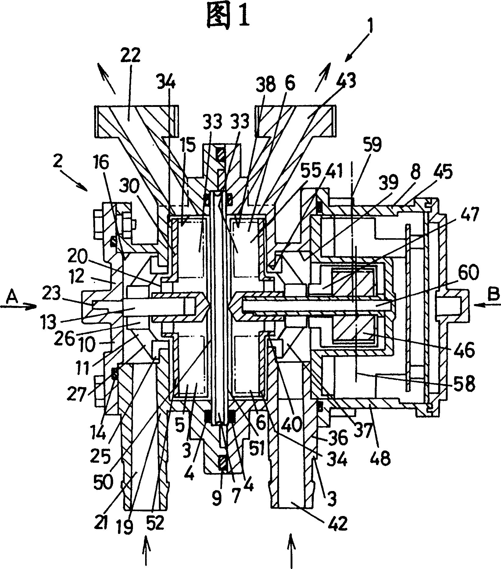
[0088] Refer to Figure 1 to Figure 9 The first embodiment of the present invention will be described.

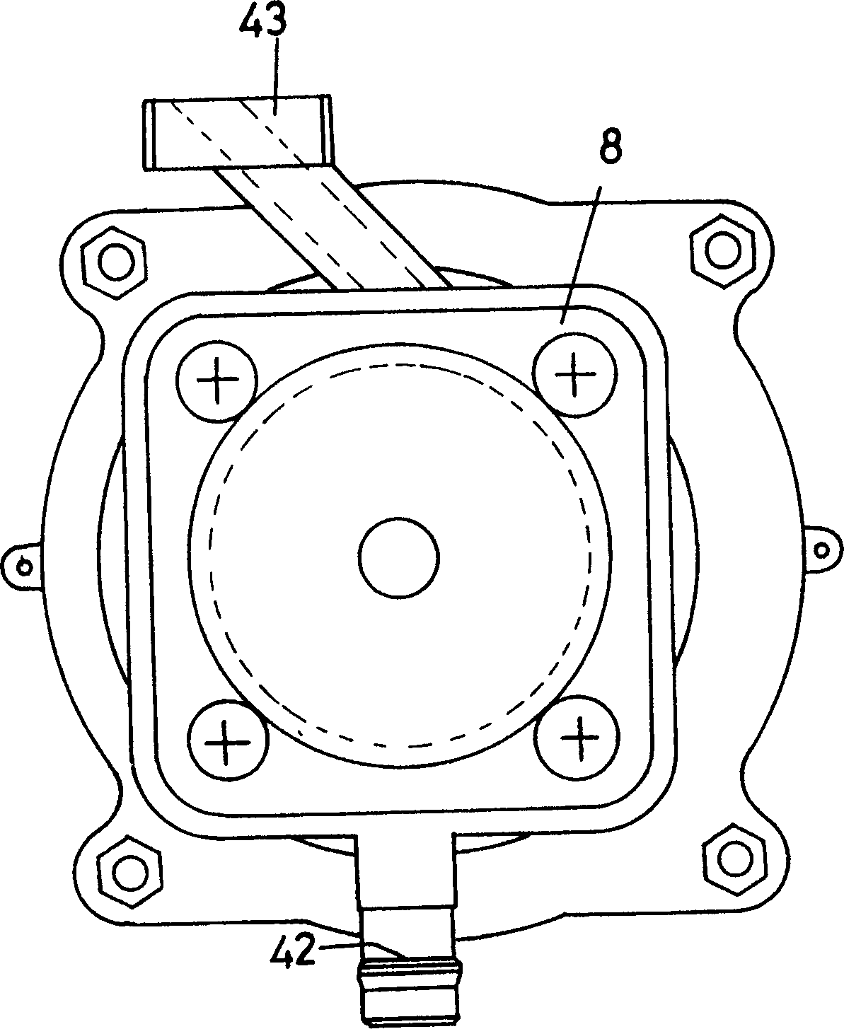
[0089] Figure 1 to Figure 9Among them, 1 is a manifold with built-in thermoelectric modules representing an embodiment of the present invention. The manifold 1 is roughly composed of the cooling-side manifold piece 2 , the heating-side manifold piece 3 , the cooling-side stirring member 5 , the heating-side stirring member 6 , the thermoelectric module 7 and the motor member 8 .

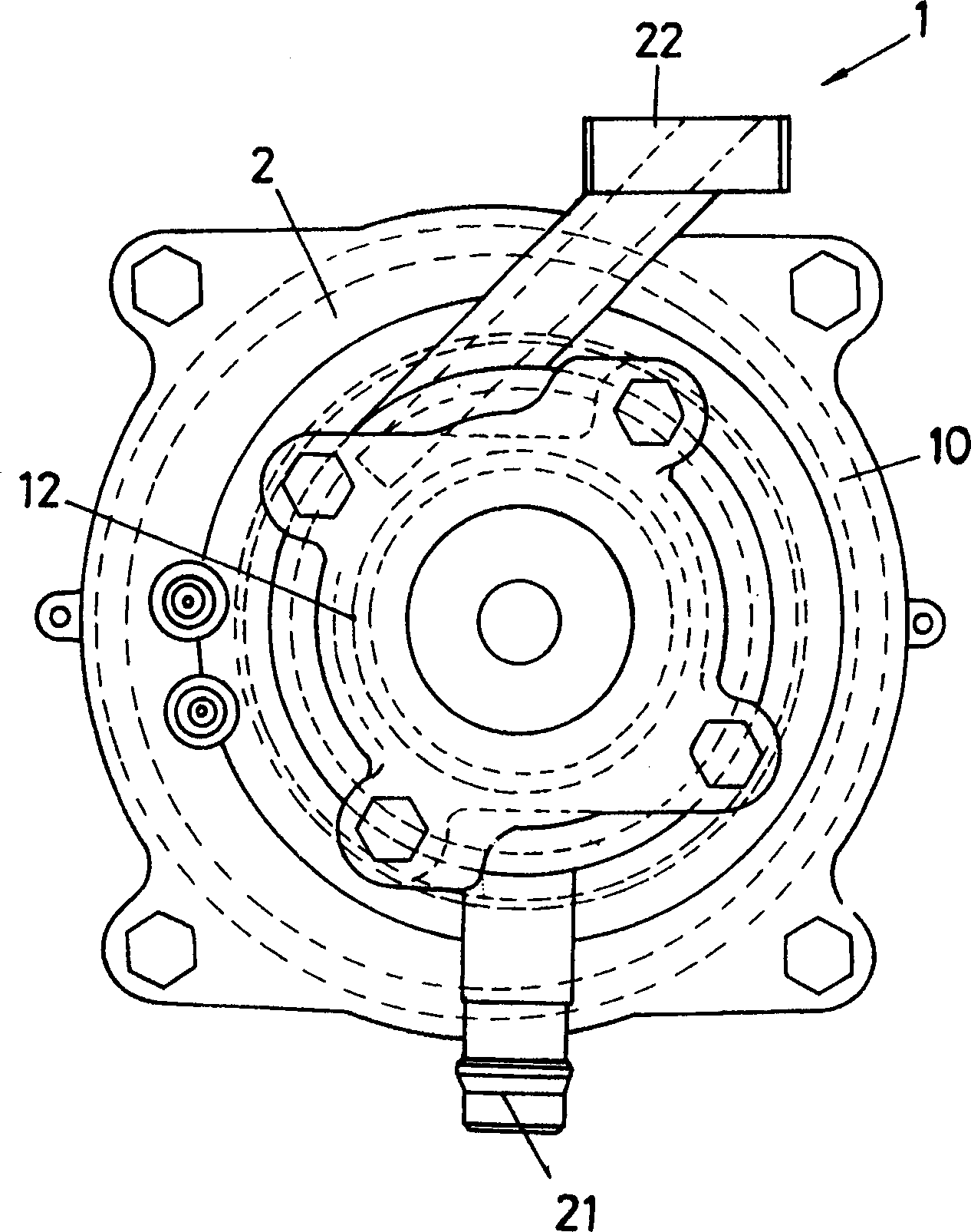
[0090] The cooling side manifold 2 is composed of a manifold body 10 , a final shaft member 11 , a cover member 12 , a shaft 13 and a seal member 14 as shown in FIGS. 1 and 4 . The outer shape of the manifold body 10 is made to have a disk-shaped portion and a hub portion.

[0091] Regarding the internal structure of the manifold body 10, a circular recess 15 is provided at a disk-shaped portion. The hub portion is also provided with a circular recess 16 . In addition, a hole 20 is provided ...

Embodiment 2

[0133] Next, a second embodiment of the present invention will be described. In the description of the second and subsequent embodiments described below, members that can perform the same functions as those of the first embodiment are assigned the same symbols, and repeated descriptions thereof are omitted.

[0134] Figure 10 It is a front sectional view of a manifold with built-in thermoelectric modules according to the second embodiment of the present invention.

[0135] The manifold 70 with built-in thermoelectric modules of this embodiment, like the previous embodiment, can transmit the rotational force of the stirring member 71 on the heating side to the stirring member 72 on the cooling side by magnetic force, but the installation position of the magnet 73 is the same as that of the previous example. different.

[0136] That is to say, in the manifold 70 of this embodiment, the areas of the cavities 74 and 75 are larger than the area of ​​the thermoelectric module 7 ....

Embodiment 3

[0139] Next, a third embodiment of the present invention will be described. Fig. 11 is a front sectional view of a manifold incorporating a thermoelectric module according to a third embodiment of the present invention.

[0140] Both of the above-described embodiments have a structure in which power is transmitted between the stirring members 5 and 6 by means of magnetic force, but in this embodiment, power is transmitted between the two by means of a shaft 78 .

[0141] That is, in the manifold 80 with built-in thermoelectric modules shown in FIG. Thus, the rotating shaft 78 is combined with the stirring member 5 on the cooling side. Thereby, the stirring member 6 on the heating side and the stirring member 5 on the cooling side are directly rotated by the rotation of the rotor 46 .


PUM


Abstract

A manifold incorporating a thermoelectric module having a wide contact of a heat medium with a heat transfer surface of the thermoelectric module and an excellent heat exchange efficiency, and a circular thermoelectric module easily manufactured and constructed into a multi-stacked structure. The manifold (1) comprises a cooling-side manifold piece (2), a heating-side manifold piece (3), a cooling-side agitating member (5), a heating-side agitating member (6), a thermoelectric module (7) and a motor member (8). Heat transfer surfaces (50, 51) of the thermoelectric module (7) are disposed vertically, so that if air enters the cavities (52, 55), air rises along the heat transfer surfaces (50, 51) and exhausted from the exhaust ports (22, 43) at the top of the manifold (1). The cooling-side agitating member (5) and the heating-side agitating member (6) are provided with permanent magnets (33), so that the cooling-side agitating member (5) receives a driving force from the heating-side agitating member (6) and is rotated. A square thermoelectric module (11) is held between aluminium disks (12,13) to form a circular thermoelectric module (10).

Description

technical field [0001] The present invention relates to manifolds incorporating thermoelectric modules. In addition, the present invention also relates to a cooling device and a thermoelectric module using a thermoelectric module. technical background [0002] In recent years, the destruction of the ozone layer by freon gas has become a global problem, and therefore, the development of cooling devices that do not use freon gas has been rapidly proceeding. Therefore, a cooling device that does not use Freon gas, which has attracted much attention, has been proposed that uses a thermoelectric module. [0003] Here, the so-called thermoelectric module refers to the well-known Peltier (Peltier) module or a component of a thermoelectric module, which has two heat transfer surfaces, and when a current flows through the component, one of the heat transfer surfaces is Heating, while the other heat transfer surface is cooled. [0004] A cooling device using a thermoelectric module...

Claims


Application Information

Patent Timeline
Patent Type & Authority Patents(China)
IPC IPC(8): F25B21/02H01L35/30
CPCH01L35/30F25B21/02H10N10/13
Inventor 井上久嘉稻森昭平藤本真嗣上辻利夫木户长生
Owner MATSUSHITA REFRIGERATION
Why Eureka
Try Eureka