A battery, process for producing battery, process for producing battery case and battery pack

A technology for battery packs and casings, which is applied in the direction of primary batteries to battery packs, battery pack components, dry batteries, etc., which can solve problems such as poor sealing, achieve improved sealing, increase productivity, and avoid strain effects

Inactive Publication Date: 2002-06-19
PANASONIC CORP
View PDF1 Cites 9 Cited by
  • Summary
  • Abstract
  • Description
  • Claims
  • Application Information

AI Technical Summary

Problems solved by technology

However, in this method, strain is generated at the corners, and thus its sealing performance is poorer than that of a cylindrical battery sealed by caulking

Method used


Image

  • A battery, process for producing battery, process for producing battery case and battery pack
  • A battery, process for producing battery, process for producing battery case and battery pack
  • A battery, process for producing battery, process for producing battery case and battery pack

Examples


example 1

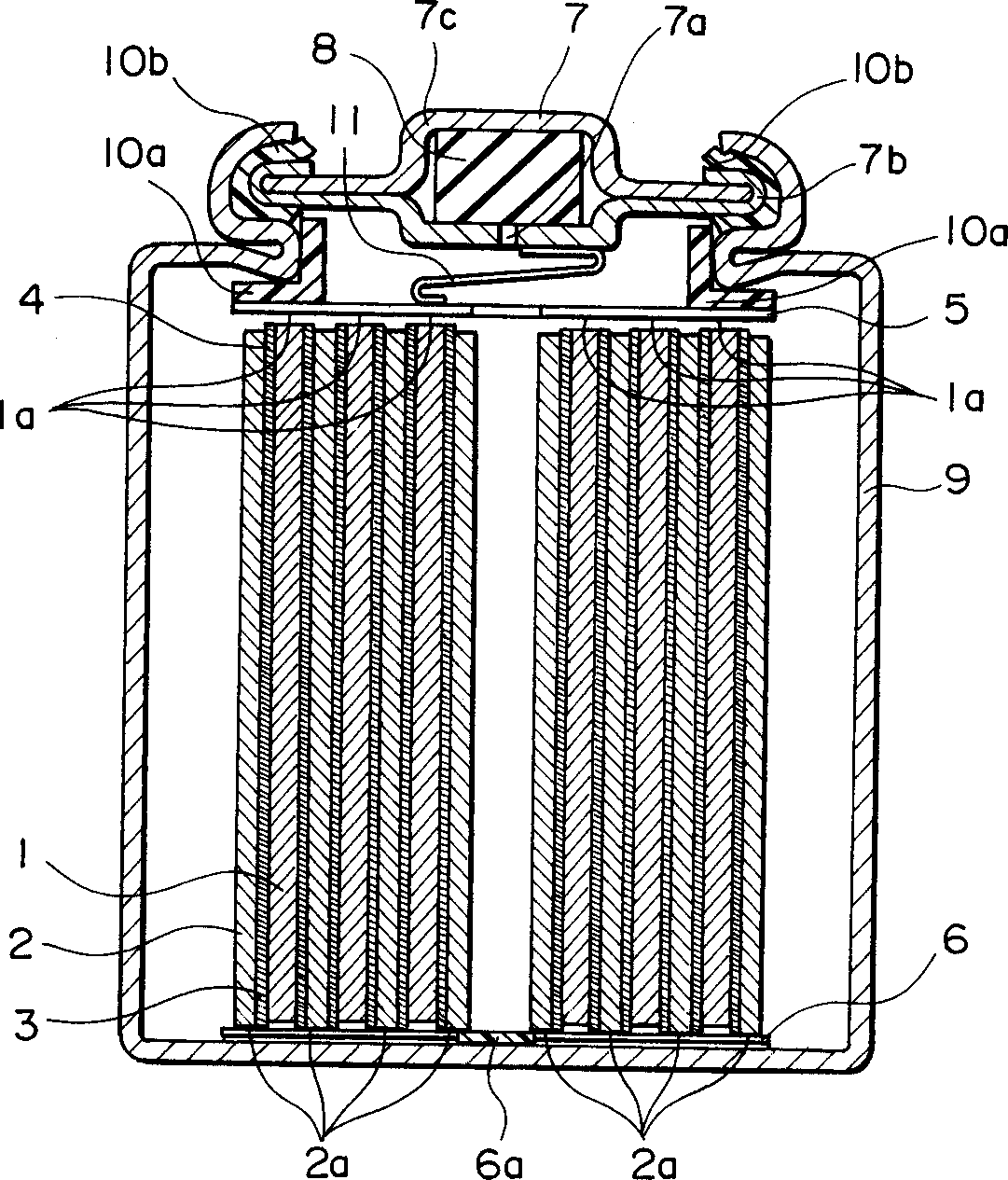
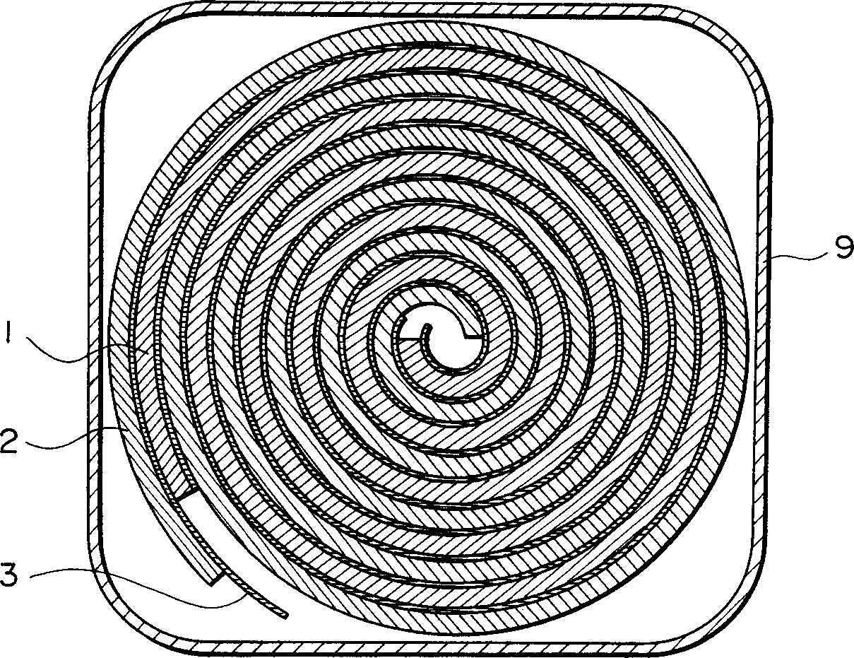
[0049] The electrical unit 4 is constructed by inserting a separator 3 between the strip-shaped positive electrode 1 and the strip-shaped negative electrode 2 and spirally winding the upwardly protruding end surface 1a of the positive electrode 1 and the downwardly protruding end surface 2a of the negative electrode 2.

[0050] The upper current collector 5 with a hole in the center is welded to the end face 1a of the positive electrode 1 of the electric unit 4 by resistance welding, and the lower current collector 6 with the tongue 6a is welded to the end face 2a of the negative electrode 2 by resistance welding.

[0051] The sealing plate 7 is constructed by arranging a filter 7b having a valve port 7a and a rubber valve body 8, and placing a cap end 7c thereon, and then welding the filter 7b and the cap end 7c by resistance welding.

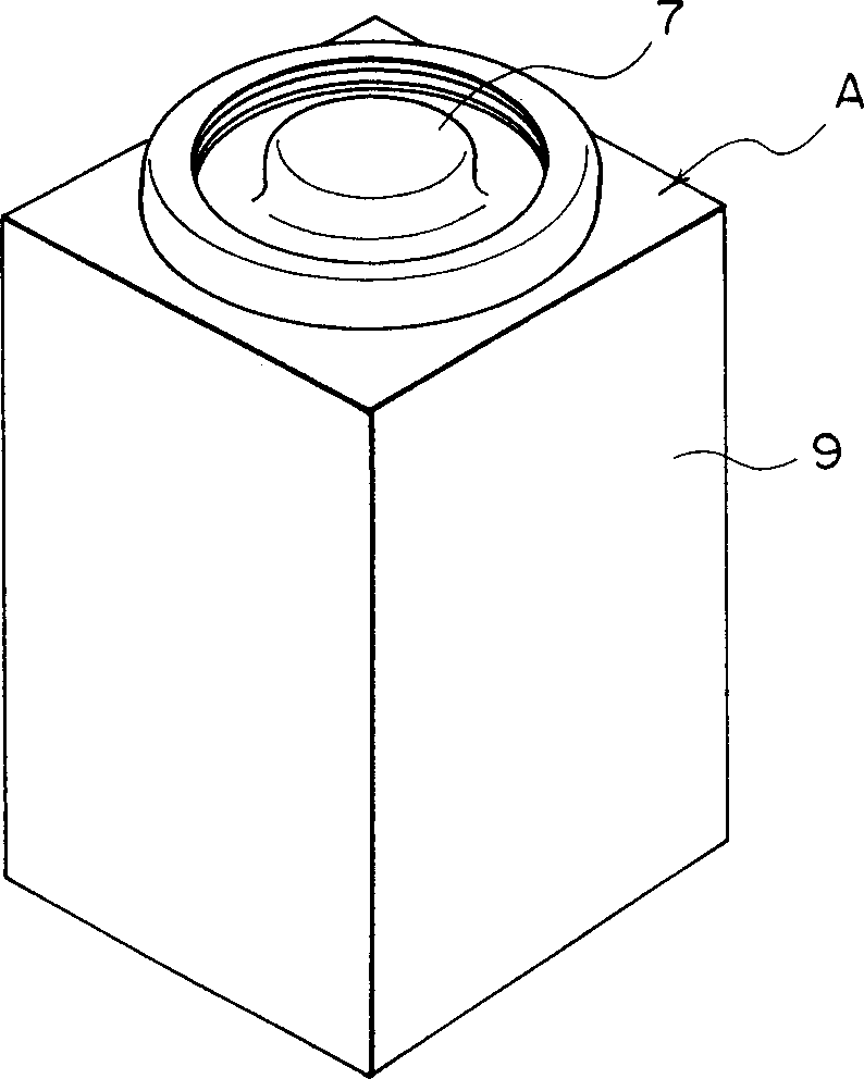
[0052] The metal battery casing 9 is made as follows: rotate the square barrel-shaped casing while pushing it from bottom to top; place its openi...

example 2

[0060] In Example 1, the described example is to insert the electrical unit only when the shape of the upper part of the battery has been formed. In this example, the battery production steps that will be described are to first insert the electrical unit and then refer to Figure 5 The schematic diagram shown forms a shell shape. In the following description, some of the reference numbers used are in Figure 5 Not shown in.

[0061] Reference Figure 5 . The electrical unit 4 is constructed by inserting a separator 3 between the strip-shaped positive electrode 1 and the strip-shaped negative electrode 2 and spirally winding the end surface of the positive electrode 1 projecting upward and the end surface of the negative electrode 2 projecting downward. The end face 1a of the positive electrode 1 of the electric unit 4 constructed as described above is welded to the upper current collector 5 having a hole in the center and the conductive sheet 11 by resistance welding. The lower cu...

example 3

[0066] Battery C was fabricated in the same manner as in Example 2, but using a hexagonal barrel-shaped casing. Figure 6 A perspective view of battery C is shown. Figure 7 A plan view of a battery pack for a power tool constructed by tightly assembling batteries C is shown. As a comparative example, a battery pack using the cylindrical battery B of the above comparative example is also Figure 7 Shown in.

[0067] It can be seen that the space utilization rate in the battery pack using the battery of the present invention is higher than that in the battery pack using the comparative example battery B, where the upper part of the battery of the present invention is circular and the lower part is hexagonal. In addition, The battery of the present invention thus makes it possible to use the space in the battery pack with higher efficiency. Example 4


PUM


Abstract

The present invention relates to a battery using a case of which the section of the lower part containing an electric element is square or hexagonal and the section of the upper part containing a sealing plate is circular or elliptic. By virtue of the shape of the lower part the space efficiency of the battery pack is enhanced and by virtue of the shape of the upper part the productivity of the battery is improved. Further, preferably, the corners of the lower part of the case are rounded or chamferred, whereby the temperature rise in the battery pack is suppressed.

Description

Technical field [0001] The invention relates to a battery, a process for producing the battery, a process for producing a battery casing, and a battery pack. Background technique [0002] In recent years, with the development of various portable devices, more and more emphasis has been placed on the development of one of the key components-the battery. Specifically, the market demand for rechargeable secondary batteries used in various devices such as mobile phones, notebook personal computers, and hybrid electric vehicles that have appeared in recent years has increased. [0003] The shape of the batteries currently used is generally cylindrical or tetragonal. [0004] When a cylindrical battery is used to construct a battery pack containing several batteries, its space efficiency is low. On the other hand, despite the high space efficiency of the battery pack, the square-pillar battery has certain difficulties in the production process. That is, the method used in the laser wel...

Claims


Application Information

Patent Timeline
Patent Type & Authority Applications(China)
IPC IPC(8): H01M6/10H01M6/44H01M10/05H01M10/30H01M10/34H01M10/40H01M10/50H01M50/209
CPCH01M2/0417H01M2/1055H01M6/44H01M10/5004H01M10/05H01M10/345H01M10/5055H01M10/5016H01M10/5012H01M10/5036H01M6/10H01M2/1066H01M10/5014H01M10/5048H01M10/5046H01M2/023H01M10/30H01M2/0217H01M10/504H01M10/5028H01M10/5053H01M10/625H01M10/653H01M10/64H01M10/6551H01M10/6552H01M10/6555H01M10/623H01M10/6554H01M10/6235H01M10/651H01M10/613Y10T29/49108Y10T29/4911Y10T29/53135Y02E60/10H01M50/56H01M50/103H01M50/154H01M50/213H01M50/209Y02P70/50
Inventor 笠原英树胜本真澄宫久正春坊木义广
Owner PANASONIC CORP
Why Eureka
Try Eureka