Safety brake iwth relative delayed brake force

A safety brake and related delay technology, used in automatic brakes, brake types, elevators, etc., can solve problems such as complex electronic adjustment devices, and achieve high reliability, easy-to-understand installation and adjustment work.

Inactive Publication Date: 2002-07-10
INVENTIO AG
View PDF1 Cites 37 Cited by
  • Summary
  • Abstract
  • Description
  • Claims
  • Application Information

AI Technical Summary

Problems solved by technology

[0007] One disadvantage of such a safety brake is that it requires a large installation area, especially the electromagnetic system, which needs to be operated by a relatively long folding arm in order to obtain a greater braking vertical positive pressure in the effective range, and, In order to ensure reliability, a very complex electronic adjustment device is also required

Method used


Image

  • Safety brake iwth relative delayed brake force
  • Safety brake iwth relative delayed brake force
  • Safety brake iwth relative delayed brake force

Examples


Embodiment Construction

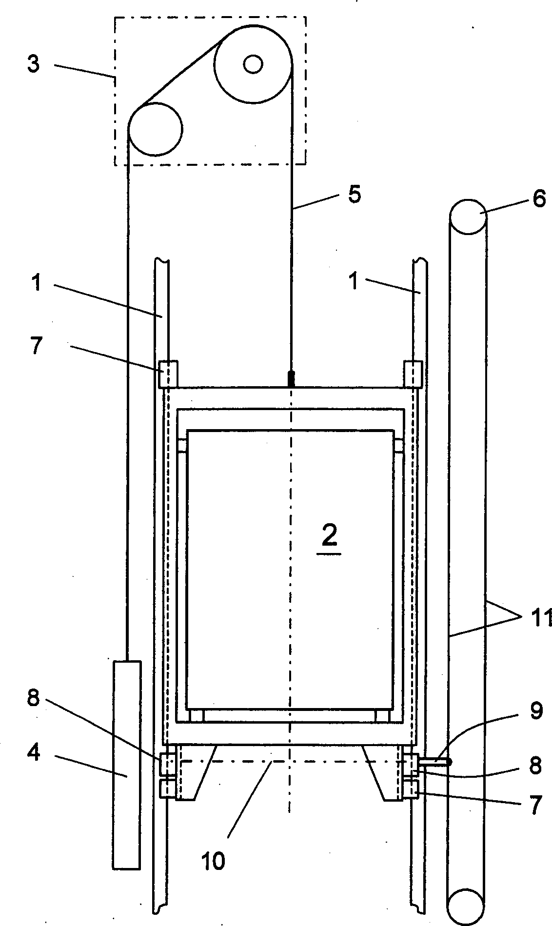
[0026] figure 1 Shown is a schematic diagram of the hoist unit including most of the important components. It can be seen that there are two guide rails 1, a load receiving device 2 on the guide rail 1 and guided by a guide block 7, a drive 3, a counterweight 4, a support cable 5, a hoisting speed limiter 6 with a speed limiter cable 11, and Two safety brakes 8 according to the invention with trigger lever 9 and trigger connection element 10 .

[0027] If the speed limiter 6 is lifted to lock the speed limiter cable 11 , then the two safety brakes 8 are triggered via the trigger lever 9 and the trigger connection element 10 , while the load receiving device 2 is also braked.

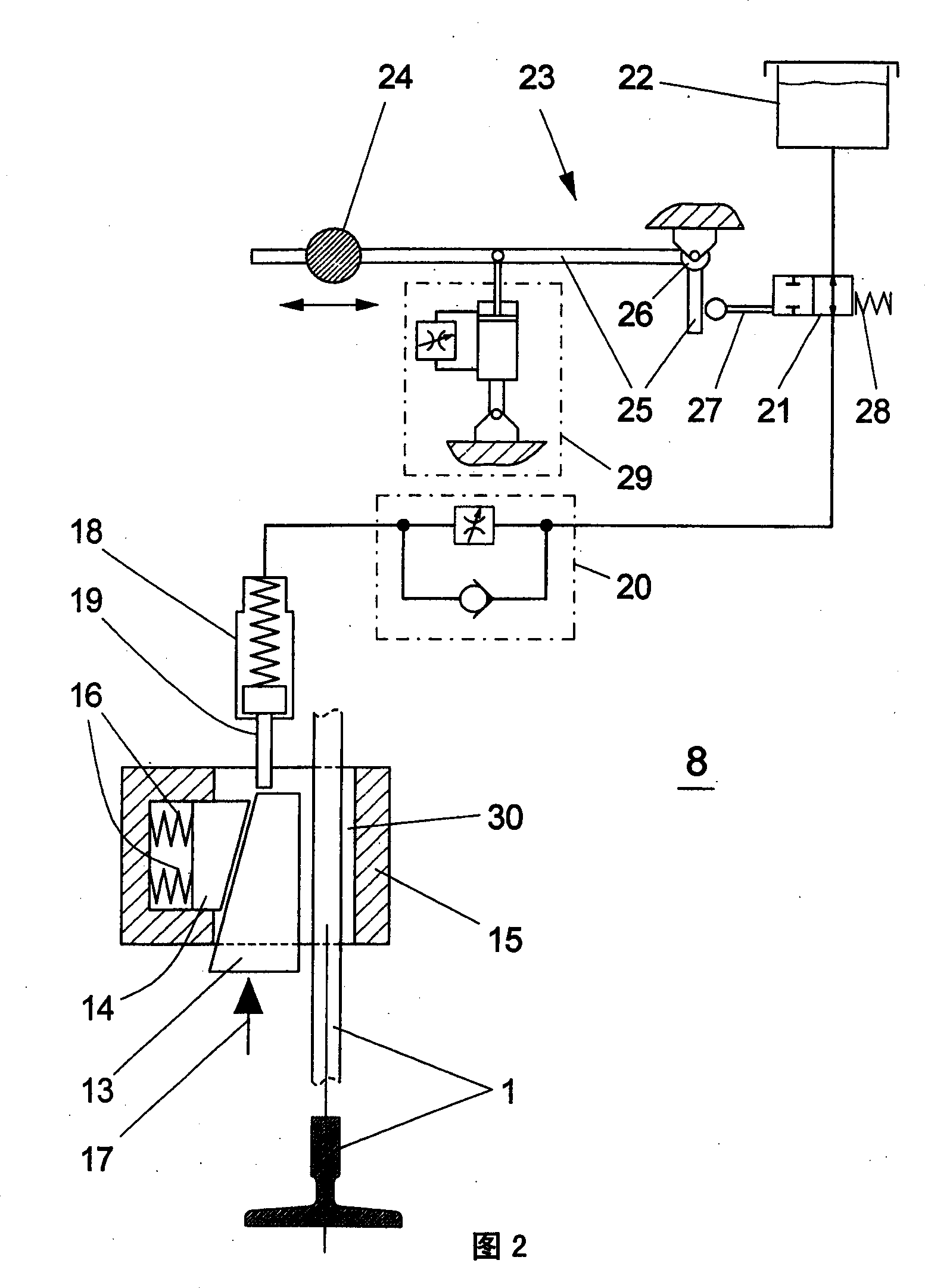
[0028]As shown in Figure 2, it can be seen that the safety brake 8 according to the present invention includes a base 15 engaged with the guide plate of the guide rail 1, and a brake inserted into the conical gap between the pressure body 14 and the guide plate of the guide rail 1. wedge13. The base 1...


PUM


Abstract

A safety brake for a load receiving means of a lift, in which at least one brake wedge (13) penetrates into a tapering gap between a resiliently supported pressure body (14) and a guide rail (1) of the load receiving means (2) and thereby generates a braki ng force, is equipped with a device (18) which limits the stroke of the brake wedge and thus the braking force in dependence on the retardation occurring at the load receivi ng means.

Description

technical field [0001] The invention relates to a safety brake with an associated delayed braking force, for a load-receiving device of an elevator, the brake is triggered by a hoisting speed limiter if the load-receiving device overspeeds, wherein the brake has at least one wedge, inserted into a The conical gap, which is located between the rebound pressure body of the safety brake and the guide rail of the load receiving device, and thereby generates a braking force, and the value of the braking force depends on the delay value of the load receiving device. Background technique [0002] Since the outer casing of the usual safety brake is only engaged with the guide plate of the guide rail of the load receiving device, and also includes at least one pressure body, one of the forms is that the guide plate and the conical gap are located at the position opposite to the moving direction of the load receiving device , while another form is to utilize movable and oppositely arr...

Claims


Application Information

Patent Timeline
Patent Type & Authority Applications(China)
IPC IPC(8): B66B1/26B66B5/22F16D59/02
CPCB66B5/22
Inventor 斯特凡·休格尔
Owner INVENTIO AG
Why Eureka
Try Eureka