Screw connection of hinge parts

A bolt and hinge technology, applied in the direction of bolts, connections, connecting components, etc., can solve problems such as high production costs

Inactive Publication Date: 2002-07-24
OBE奥马赫特&鲍姆格特纳有限公司
View PDF0 Cites 14 Cited by
  • Summary
  • Abstract
  • Description
  • Claims
  • Application Information

AI Technical Summary

Problems solved by technology

A further disadvantage is that the through-holes in the hinge parts have to be drilled separately and, if necessary, threaded, which results in higher production costs for this bolted connection

Method used


Image

  • Screw connection of hinge parts
  • Screw connection of hinge parts
  • Screw connection of hinge parts

Examples


Embodiment Construction

[0024] Now in conjunction with accompanying drawing, the present invention is described in detail as follows:

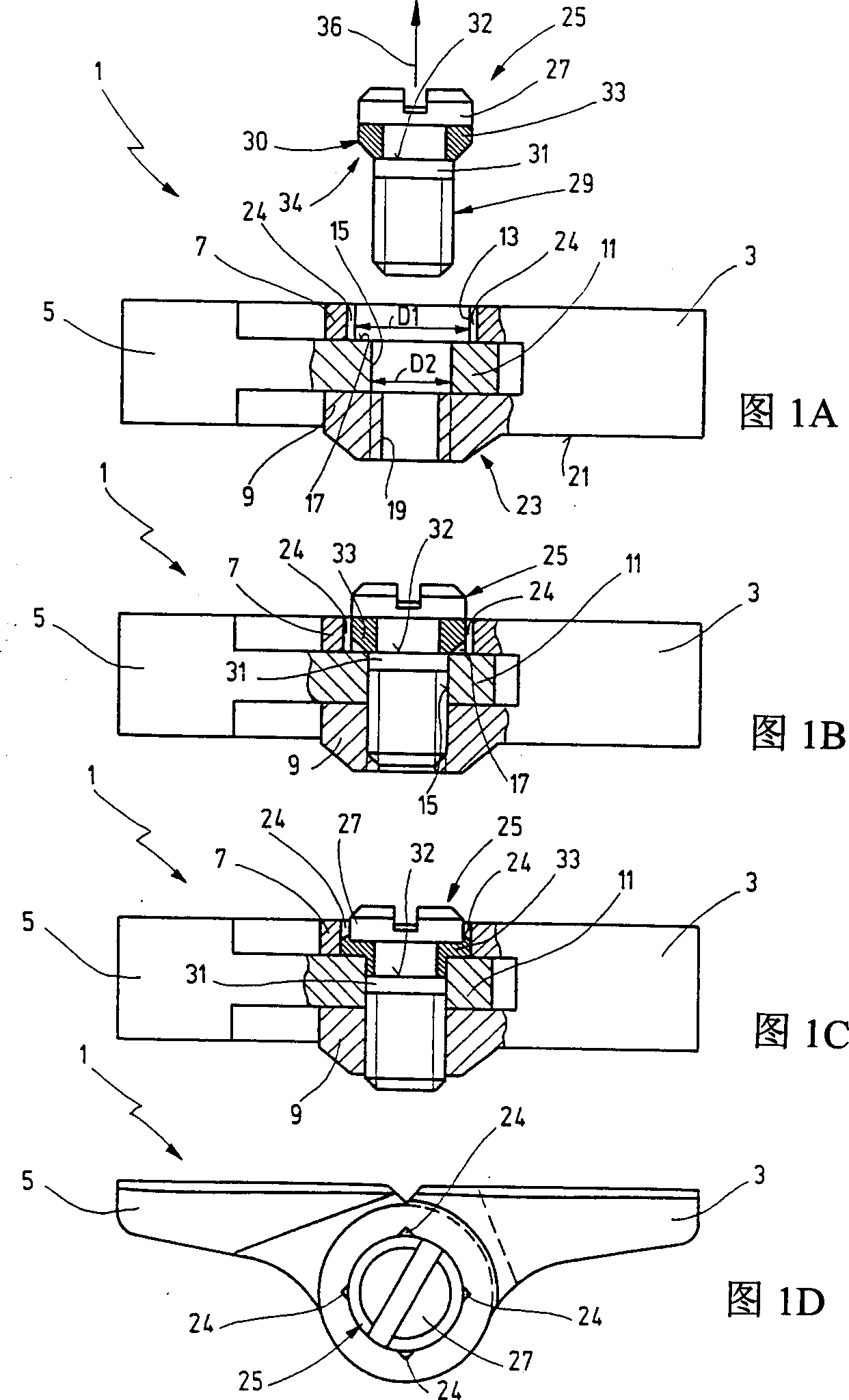
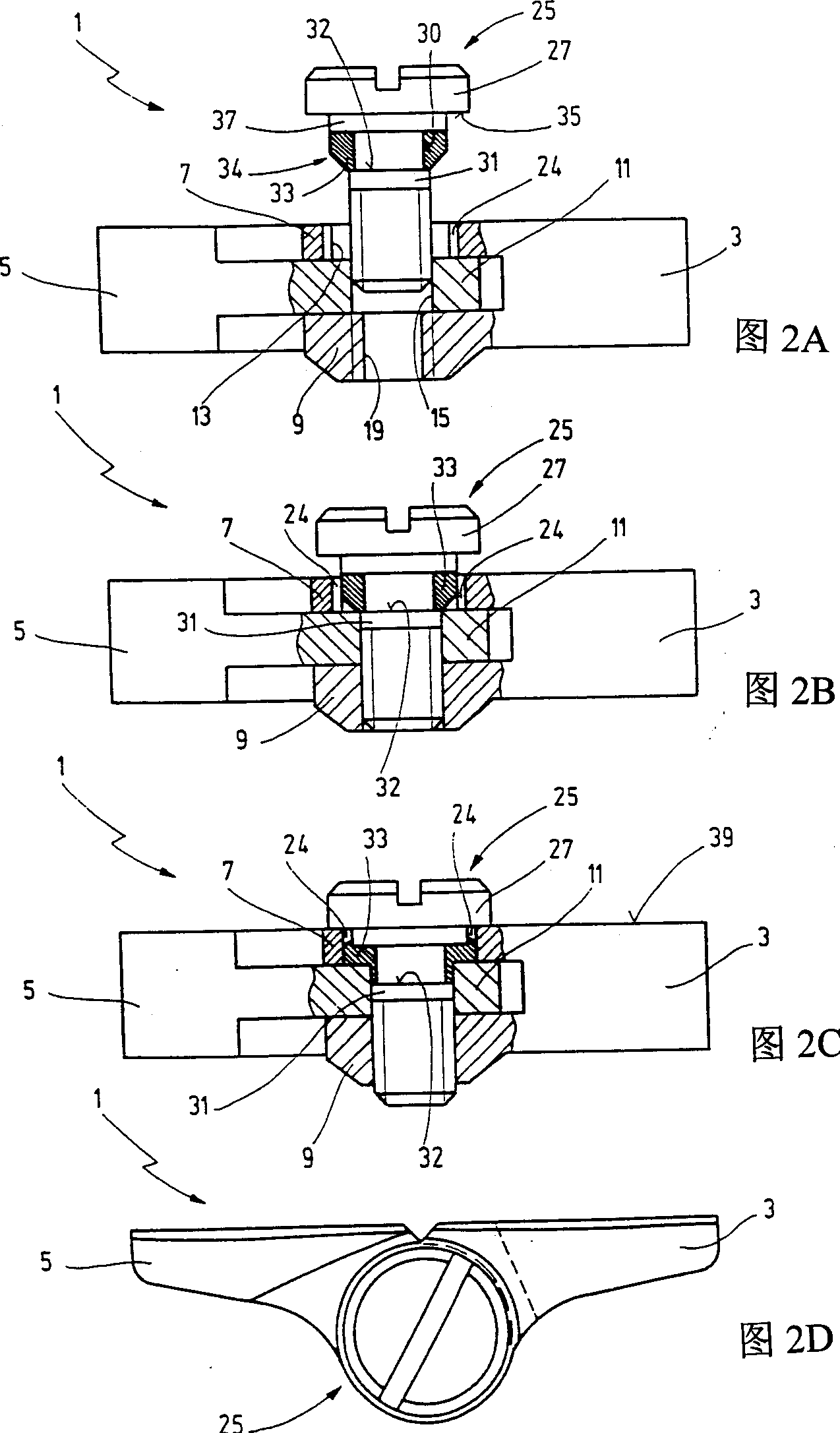
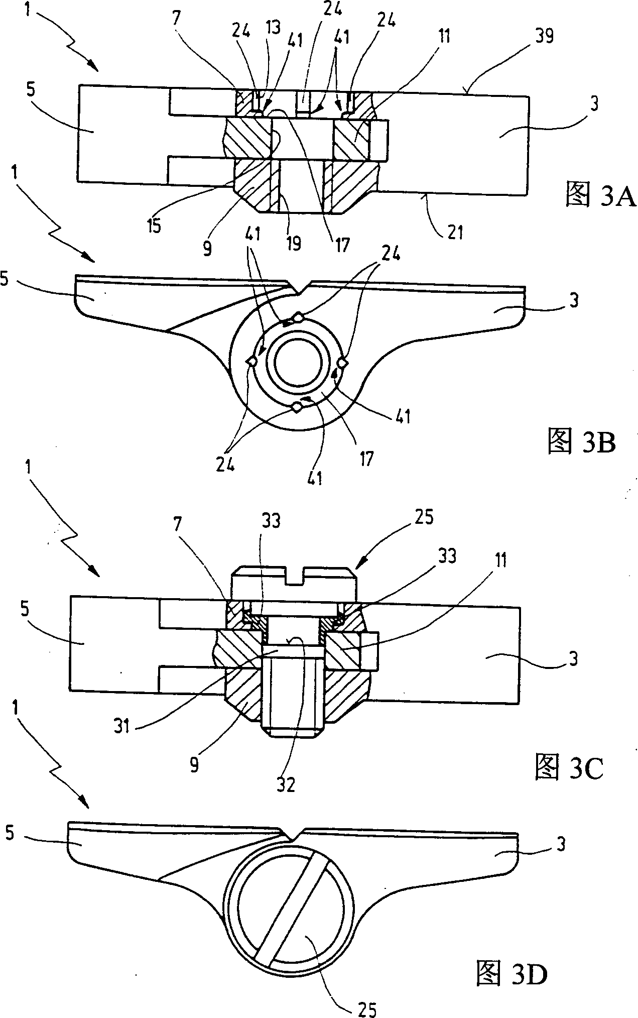
[0025]FIG. 1A shows a longitudinal section through a screw connection 1 of a hinge part, such as a spectacle frame, comprising a double-leaf hinge 3 and a single-leaf hinge 5 which are inserted into each other. Assume that the double-piece hinge 3 is connected with the spectacle frame, and the single-piece hinge 5 is connected with the spectacle leg. The double-leaf hinge 3 has an upper hinge lug 7 and a lower hinge lug 9, while the single-leaf hinge 5 has a middle hinge lug 11 between the upper and lower hinge lugs 7 and 9, the smaller the gap the better . A first through hole 13 emerges from the upper hinge lug 7 and a second through hole 15 emerges from the middle hinge lug 11 so that the longitudinal axes of said through holes are concentric. The through-holes 13 and 15 are designed here as circular cross-sections. In another embodiment, the cross section of t...


PUM


Abstract

A screw connection for hinge parts, especially of an eyeglass frame, comprising a screw that interconnects the hinge parts that engage one inside the other and that have an upper hinge lobe, a lower hinge lobe, and at least one middle hinge lobe, the screw having a screw head and a screw shank that extends through a first through opening in the upper hinge lobe and extends through a second through opening in the middle hinge lobe, with a thread permitting the screw shank to be screwed into the lower hinge lobe, and comprising a sleeve that surrounds the screw shank, has elastic properties, and interacts with the upper and middle hinge lobes when the screw is in a screwed-in state, whereby the diameter (D 2 ) of the second through opening is less than or equal to the diameter (D 1 ) of the first through opening. The screw connection is distinguished by the fact that the screw ( 25 ) has at least one bearing surface for the sleeve ( 33 ) with at least one engaging surface ( 32 ) that is aligned in the direction of movement in which the screw ( 25 ) is unscrewed.

Description

technical field [0001] The invention according to the preamble of claim 1 relates to a screw connection of hinges, in particular of spectacle frames. Background technique [0002] DE-AS1196397 describes a bolted connection of the type comprising a bolt connecting two hinge parts. The bolt passes through a cylindrical through hole of the upper hinge lug and a conically tapered through hole of the middle hinge lug, and can be pre-screwed by means of the thread of the lower hinge lug. The bolt shank is surrounded by a plastic bushing which is compressed when the bolt is tightened, whereby the bushing is pressed against the wall of the through-hole of the middle hinge lug to accommodate this movement. The disadvantage is that this material of construction is bulky, resulting in a larger outside diameter of the bushing. Consequently, the normally required miniaturization is not possible due to the large diameter of the hinge eye. Obviously, when the bolts are loosened from the...

Claims


Application Information

Patent Timeline
Patent Type & Authority Applications(China)
IPC IPC(8): F16B35/04F16B39/282F16C11/02G02C5/22
CPCG02C5/2281F16B35/048F16C11/02F16B39/282Y10T403/32909Y10T403/32918
Inventor 克劳斯·贝赫赖纳·瓦格纳
Owner OBE奥马赫特&鲍姆格特纳有限公司
Why Eureka
Try Eureka