Disk brake of bicycle

A technology for bicycles and moving discs, applied to bicycle accessories, bicycle brakes, etc., can solve the problems of high manufacturing cost, drag torque, difficult processing of driving discs and fixed discs, etc., and achieve cost reduction, compact structure and flexible braking Effect

Inactive Publication Date: 2002-08-14
许艳
View PDF1 Cites 4 Cited by
  • Summary
  • Abstract
  • Description
  • Claims
  • Application Information

AI Technical Summary

Problems solved by technology

The disadvantages are that the structure of the driving device is complicated, the driving disc and the fixed disc are not easy to process, the manufacturing cost is high, the return position of the disc brake is not ideal when braking, and it is easy to generate dragging torque

Method used


Image

  • Disk brake of bicycle
  • Disk brake of bicycle
  • Disk brake of bicycle

Examples


Embodiment 1

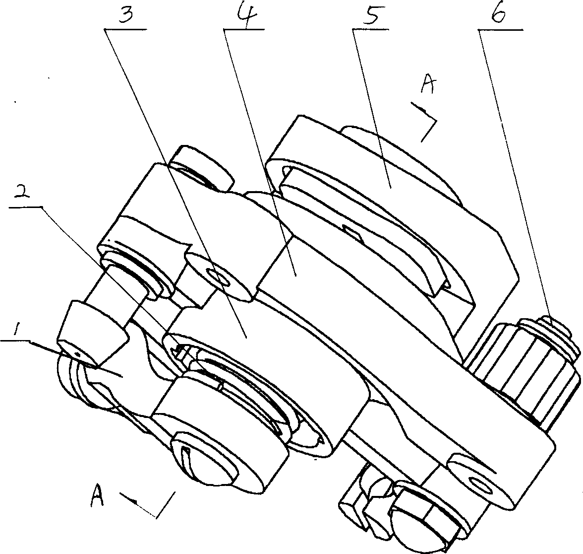
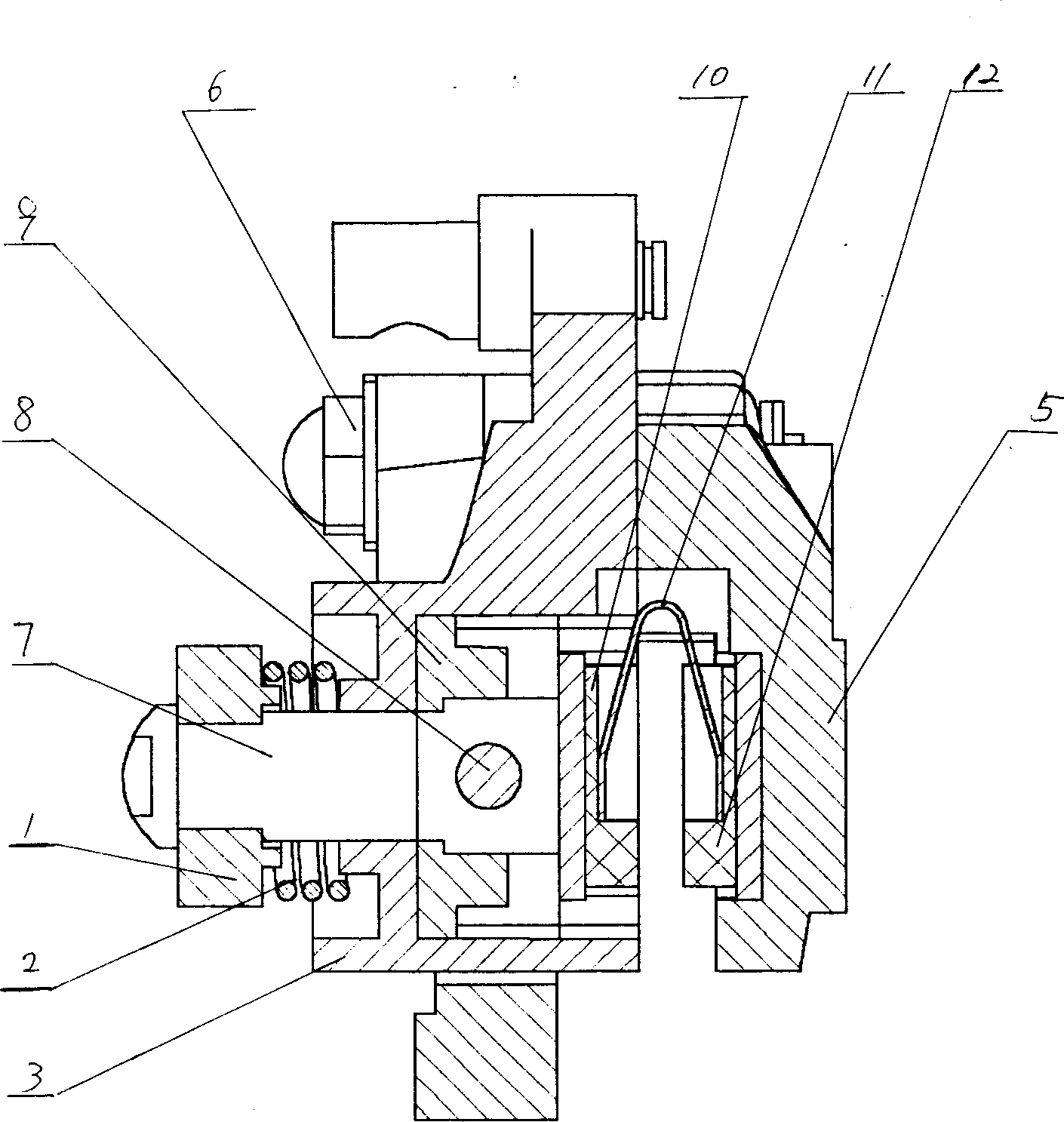
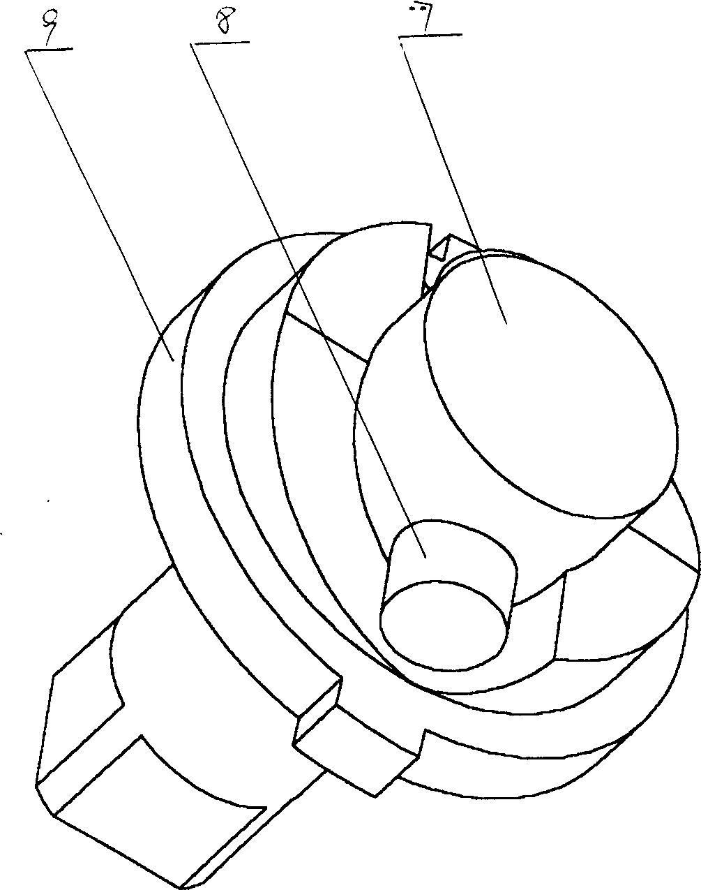
[0023] Embodiment one, the specific implementation mode of the present invention is as figure 1 , figure 2 , image 3 , Figure 4 Shown: a kind of bicycle disc brake, it comprises brake brake driving device and brake brake caliper body 5, a pincer arm of brake brake caliper body 5 is fixedly connected with housing 3 of brake brake drive device, in brake brake caliper body 5 Left and right friction plate assemblies 10, 12 are installed, and a V-shaped leaf spring 11 is arranged between the two friction plate assemblies. The housing 3 of the brake drive device is provided with a drive shaft 7 perpendicular to the friction plates. One end of the drive shaft 7 is connected to the right friction plate assembly, the other end of the drive shaft 7 protrudes from the housing 3, and a rocker arm 1 is installed at its end, and a return spring 2 is installed between the rocker arm 1 and the housing 3 , the casing 3 is equipped with a fixed disk 9 that is sleeved on the drive shaft 7 ...

Embodiment 2

[0024] Embodiment 2. In the above embodiment, the two drive pins on the drive shaft 7 are fixedly connected as a whole. Such as Figure 5 As shown, another embodiment of the present invention is that a bearing 14 that rotates concentrically with the center line of the pin shaft is respectively installed at the end of each driving pin 8 .

Embodiment 3

[0025] Embodiment three, such as Figure 6 As shown, in the third embodiment of the present invention, a spherical crown-shaped groove is opened on the surface corresponding to the end of each driving pin 8 and the fixed plate 9, and steel balls 15 are housed in the spherical crown-shaped groove. The frictional resistance can also be partially reduced through steel ball transmission, increasing the flexibility of operation and the return effect.


PUM


Abstract

A disk brake for bicycle is composed of braking driver, braking clamp left and right friction blocks installed in said clamp, and braking disk installed between said friction blocks. The one end of drive axle of said driver is linked to right friction block and its another end is extended out of the casing. A rockerarm is installed to the extended end. A release spring is installed between rockerarm and casing. Said friction blocks are driven by said drive axle to realize braking. Its advantages include compact structure, flexible braking and low cost.

Description

technical field [0001] The invention relates to a bicycle braking device, in particular to a bicycle disc brake. Background technique [0002] In the prior art, such as the Chinese patent whose patent application number is 01245238.6, a bicycle disc brake includes a brake drive device and a brake caliper body, and left and right friction plate assemblies are installed in the brake caliper body. A bicycle brake disc is installed between the plate components, and the brake caliper body is fixedly connected with the housing of the brake driving device. The brake driving device is installed on the bicycle frame through the mounting seat, and the brake driving device housing is provided with Drive shaft, one end of the drive shaft extends into the brake caliper and connects with the right friction plate assembly, the middle part of the drive shaft is fixed with a drive disc, the other end of the drive shaft extends out of the housing, and a rocker arm is in...

Claims


Application Information

Patent Timeline
Patent Type & Authority Applications(China)
IPC IPC(8): B62L1/02
Inventor 许艳
Owner 许艳
Why Eureka
Try Eureka