Booster and press working device
A technology of processing device and supercharger, applied in fluid pressure actuating devices, presses, fluid pressure converters, etc., can solve problems such as increasing energy consumption
- Summary
- Abstract
- Description
- Claims
- Application Information
AI Technical Summary
Problems solved by technology
Method used
Image
Examples
no. 1 example
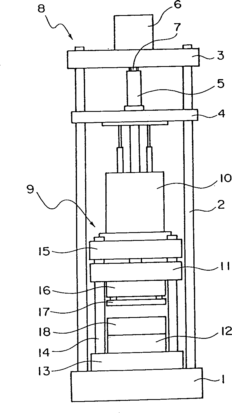
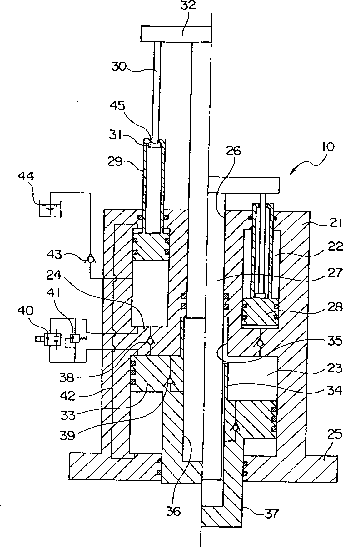
[0083] The first embodiment of the present invention has the following effects:
[0084] 1) The stroke of the movable die required for press processing parts can be relatively large. This allows the moveable mold to be moved at relatively high speed through the range of motion with a small actuation force, thereby applying a large actuation force between relatively short strokes in the final stage.
[0085] 2) The operating device requires a very small amount of hydraulic oil, and since it is not necessary to supply high-pressure hydraulic oil to hydraulic components, etc., it requires very little energy consumption.
[0086] The first embodiment described above has a structure in which the cavity 36 and the protrusion 34 are located on the actuating piston 33 . The actuating piston 33 can descend at the same descending speed as the plunger 27 until the protruding member 34 passes the bottom end of the sliding member 35 extending continuously toward the upper part of the cyli...
no. 2 example
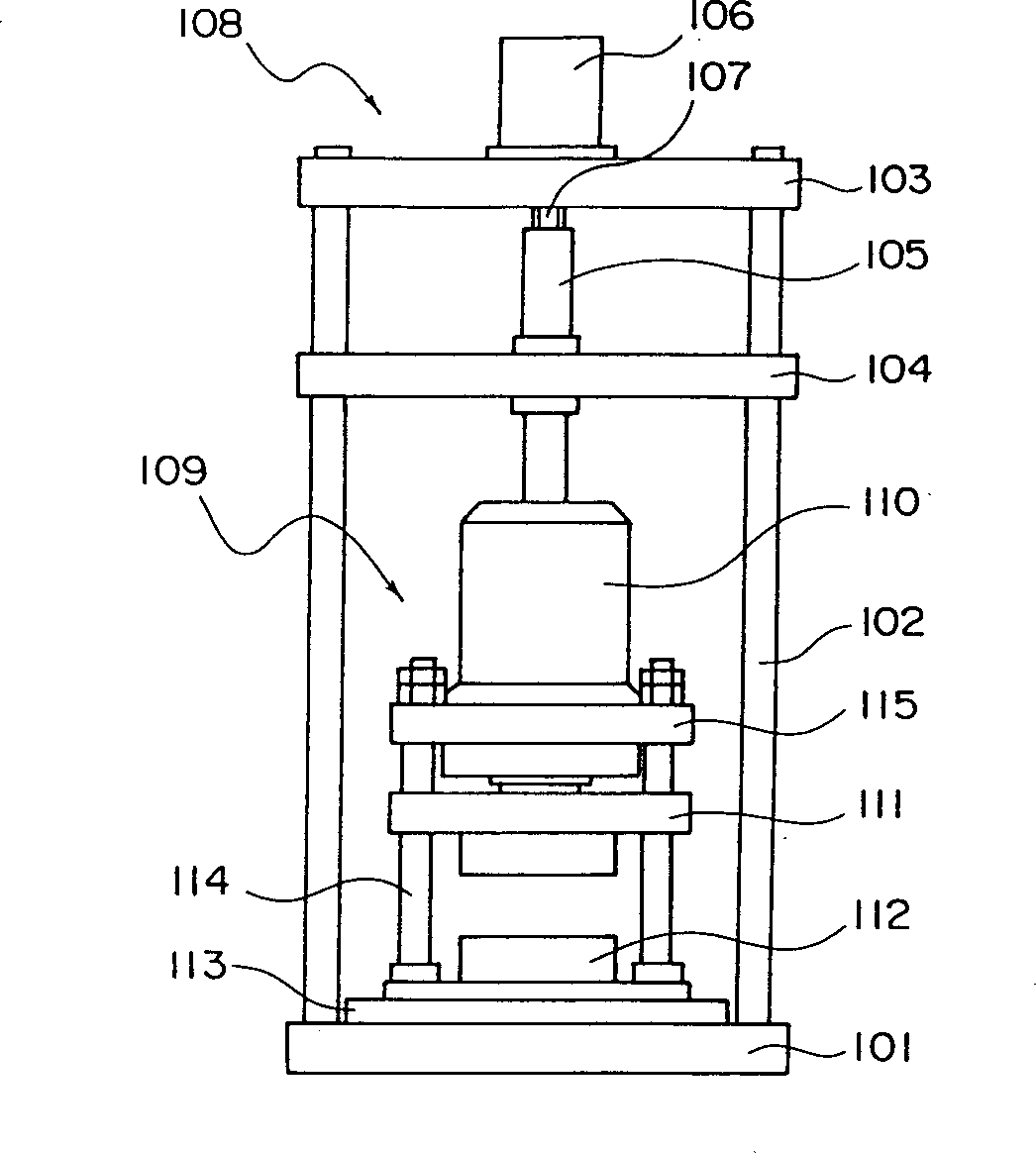
[0111] The second embodiment of the present invention has the following effects:
[0112] A) The second piston 124 descends at the same descending speed as the first piston 123 until the upper end of the protruding part 125 that is positioned on the top of the second piston 124 and is integrally formed with it passes through the downwardly moving, communicating first cylinder 121 and the first cylinder 121. Part of the second cylinder block 122 . That is, since the pressure in the cavity of the second cylinder above the second piston 124 is low during this period, hydraulic oil is supplied thereto from the oil tank 138 by means of the check valve 141 . In addition, hydraulic oil is discharged from the cavity of the second cylinder below the second piston 124 into the oil tank 133 by means of the switching valve 134 and the one-way valve 141 during this period. Therefore, the second piston 124 descends at the same speed as the first piston 123 .
[0113] B) When the upper end...
no. 3 example
[0139] The third embodiment of the present invention can obtain following effects:
[0140] 1) The stroke of the movable mold required by press processing parts is relatively large, which allows the parts to move at relatively high speeds, especially when only small driving forces are required, and allows the parts to produce large dies in a relatively short stroke in the final stage. driving force.
[0141] 2) Since the actuation piston 226 and rod 227 are loaded from below due to the presence of the workpiece, a predetermined large actuation force is generated at any position between the beginning and the end of the movable part.
[0142] 3) Because the operating device requires a very small amount of hydraulic oil, the energy consumption is extremely small, and there is no need to supply high-pressure hydraulic oil to the hydraulic components.
PUM
 Abstract
Description
Claims
Application Information
 - R&D
- Intellectual Property
- Life Sciences
- Materials
- Tech Scout
- Unparalleled Data Quality
- Higher Quality Content
- 60% Fewer Hallucinations
Browse by: Latest US Patents, China's latest patents, Technical Efficacy Thesaurus, Application Domain, Technology Topic, Popular Technical Reports.
© 2025 PatSnap. All rights reserved.Legal|Privacy policy|Modern Slavery Act Transparency Statement|Sitemap|About US| Contact US: help@patsnap.com


