Electronic element installation device

An electronic component installation, electronic component technology, applied in the direction of electrical components, electrical components, electrical components assembling printed circuits, etc., can solve the problems of increased size and number of components, shortened life of leads 8, increased costs, etc., to reduce the number of parts. , the effect of shortening the rotation time and simplifying the structure

Inactive Publication Date: 2002-10-02
PANASONIC CORP
View PDF0 Cites 8 Cited by
  • Summary
  • Abstract
  • Description
  • Claims
  • Application Information

AI Technical Summary

Problems solved by technology

[0012] Nevertheless, the conventional electronic component mounting device still has the following problems: one is to increase the rotating speed of the driver 3 in order to reduce the cycle time of the electronic component mounting device, or in other words, to change the mounting direction of the electronic component Rotation, in order to reduce the time required for rotating body 1 to rotate, it is necessary to increase its rotational speed
[0016] Due to the increase of vibration and the expansion and contraction speed of the coil segment 31, the contact force between the turns of the coil will increase when the coil segment 31 expands and contracts, and the life of the lead wire 8 will be shortened.
[0017] In addition, in order to rotate the rotary body 1, it is necessary to provide a driving connection device 2 in addition to the driver 3, and to deal with the wiring problem of the lead wire 8, a lead wire arrangement device must be provided, which will increase the size of the equipment and the number of components and cause cost increase

Method used


Image

  • Electronic element installation device
  • Electronic element installation device
  • Electronic element installation device

Examples


Embodiment Construction

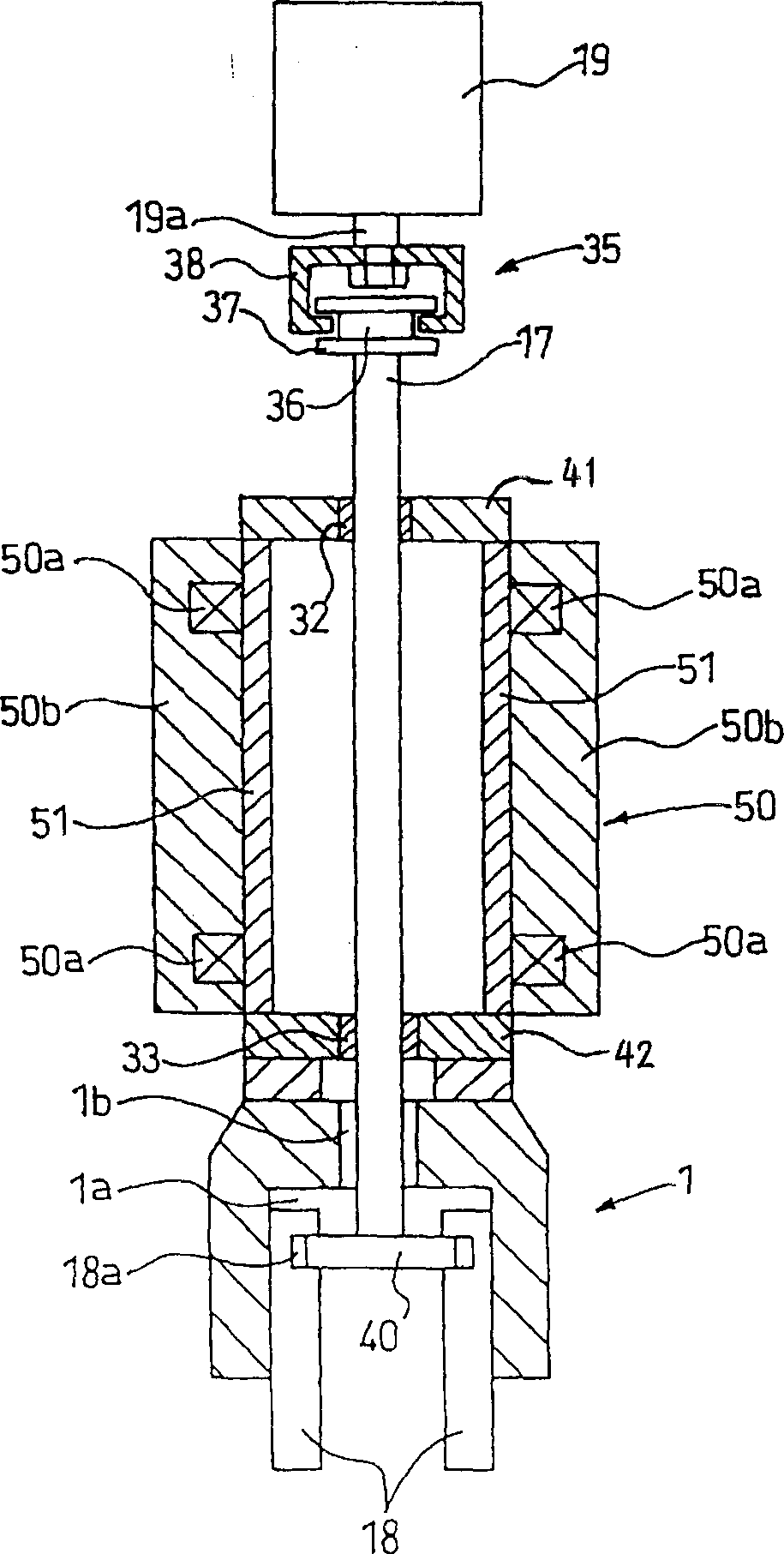
[0034] Combine below figure 1 A first embodiment of the electronic component mounting apparatus of the present invention will be described. figure 1is a cross-sectional view showing the structure of a rotating body which is a part of the electronic component mounting device. The reference numerals used in the foregoing description and in the example electronic component mounting apparatus 100 of the prior art will also be applicable to the description of the present embodiment.

[0035] As with the previous technique example, shown in figure 1 The rotating body 1 at the lower part installs various electronic components successively on predetermined positions of the bottom plate in different installation directions. A hollow motor 50 is arranged above the rotating body 1 , the flange 42 is inserted between the hollow motor 50 and the rotating body 1 , and a driver 19 is arranged above the rotating body 1 . The hollow motor 50 has a stator 50b, and a coil 50a is wound arou...


PUM


Abstract

The invention relates to an electronic component mounting device. In this device, there is a rotating body used to change the direction of the component mounting part. The rotating body is fixed on a hollow rotating shaft through an intermediate flange. The hollow shaft is arranged on a hollow motor and drives the hollow motor to rotate. The whole body rotates. An electronic component used to change the direction of the component mounting part is arranged in the rotating body, and a lead wire extends from the electronic component, and is in a loose state or in a spiral shape in the hollow rotating shaft. The lead wire is arranged in the hollow body used to change the direction of the component installation part, and one end of the lead wire is fixed on the rotating body. In addition, the inner surface of the hollow rotating body and the surface of the coupling shaft are covered with protective materials.

Description

technical field [0001] The present invention relates to an electronic component mounting apparatus for mounting electronic components on a chassis, and more particularly to a rotary drive as part of the electronic component mounting apparatus and a method of dealing with wiring problems. Background technique [0002] Combine below Figure 4 The configuration of a conventional electronic component mounting apparatus 100 will be described. [0003] The rotating body 1 successively installs various electronic components on predetermined positions on the bottom plate in different installation directions. The rotating body 1 is connected with the driver 3 through a first driving connection device 2, and is designed to enable the driver 3 to drive the rotating body 1 to rotate a reciprocating amount of a predetermined angle. The driver 3 is fixed on a fixed structure not shown in the figure such as a frame. [0004] A component mounting part 18 is arrange...

Claims


Application Information

Patent Timeline
Patent Type & Authority Applications(China)
IPC IPC(8): H05K7/00H05K13/04
CPCH05K13/0413Y10T29/4913Y10T29/53174Y10T29/53178Y10T29/53183
Inventor 横山大渡边英明金井圣小山利幸石井平
Owner PANASONIC CORP
Why Eureka
Try Eureka