
Dental tooth drill

A dental and rod technology, applied in the direction of dental drilling, dentistry, dental tools, etc., can solve the problems of insufficient flexibility, increased manufacturing cost, strong machinability, etc.

Inactive Publication Date: 2002-10-09
MATSUTANI SEISAKUSHO CO LTD
View PDF0 Cites 6 Cited by
  • Summary
  • Abstract
  • Description
  • Claims
  • Application Information

AI Technical Summary

Problems solved by technology

For example, NiTi tooth files have high flexibility, but due to the characteristics of shape memory alloys, elongation and deformation rarely occur, and it is difficult to visually confirm the fatigue state of the working part
Therefore, it may be damaged suddenly during the procedure for root canal formation
[0011] In addition, when manufacturing NiTi tooth files, the working part must be processed on the material that has undergone shape memory treatment, but since the plastic working method cannot be used, when the torsion shape of the working part is to be formed, twisting processing cannot be used, and one side has to be used. A complex processing method that moves the material and the grinding device relative to each other while grinding the material
As a result, the problem of a substantial increase in manufacturing costs also arises
[0012] The engine drill, due to its insufficient flexibility, cannot cut along the root canal and deviates, or the cutting is too strong and invades the root canal wall, which cannot form a good root canal

Method used


Image

  • Dental tooth drill
  • Dental tooth drill
  • Dental tooth drill

Examples


Embodiment Construction

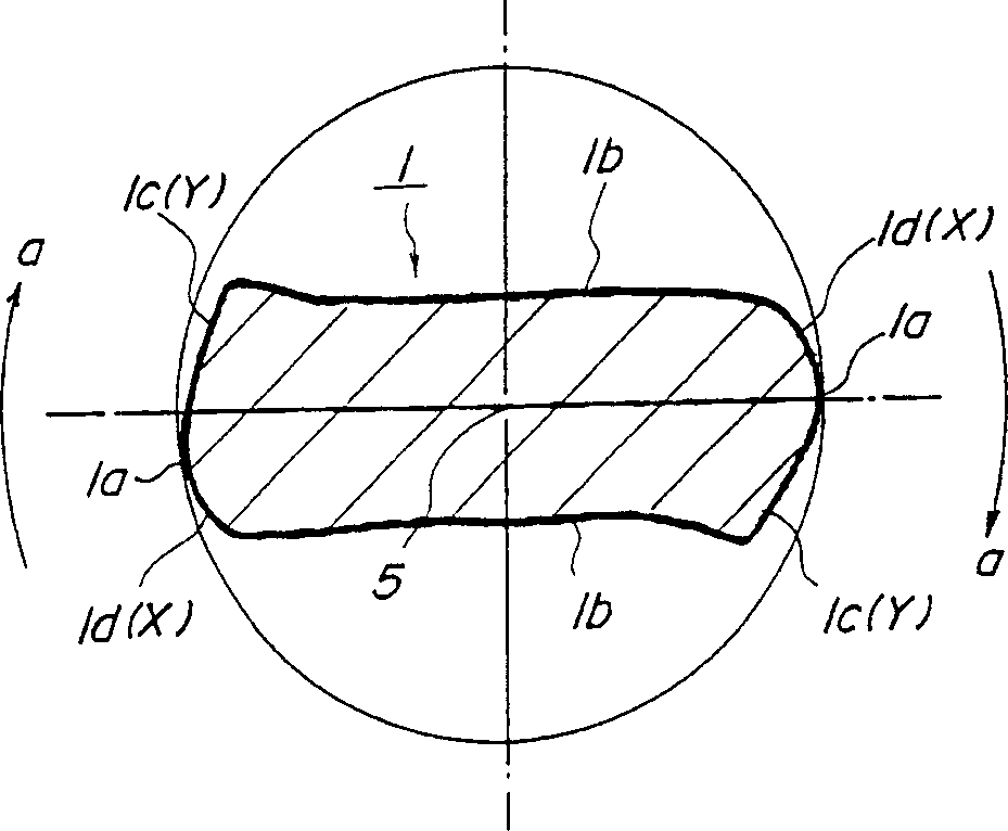
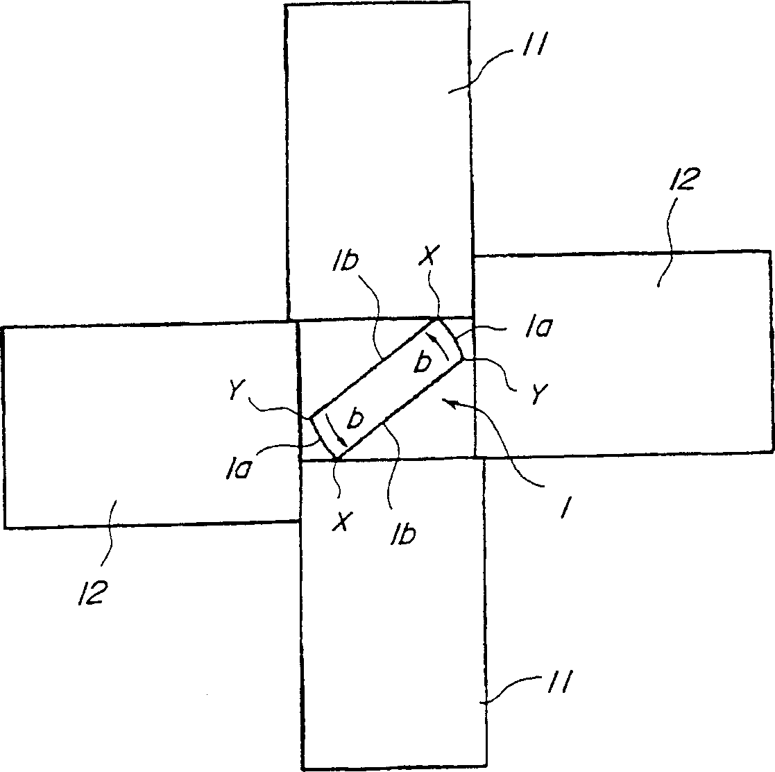
[0033] The preferred implementation forms of the above-mentioned dental drill are described below in conjunction with the accompanying drawings. figure 1 It is an explanatory diagram of the overall structure of the drill. figure 2 It is to describe the cross-sectional shape of the working part figure 1 II-II direction view. image 3 It is a schematic diagram illustrating an example of a twist forming device used when forming a working part. Fig. 4 is an explanatory diagram of a cross-sectional shape of an intermediate material. Fig. 5 is a cross-sectional view of a working portion formed by twisting an intermediate material having the cross-sectional shape of Fig. 4 . Fig. 6 shows the result of forming a root canal with the drill of this embodiment, the NiTi file and the engine drill. Figure 7 It is to compare the time required for root canal formation with a plurality of test pieces of the size number No. 20 (tip diameter 0.2 mm) of the present invention, NiTi file and ...


PUM


Abstract

A dental drill (A) grinds a tapered rod with two opposite lines (1b), thereby forming a rod with two arcs (1a) and a center (5). This rod is inserted into a forming space formed by a pair of pressing clamps (11) and a supporting clamp (12) and then twisted, thereby forming a spiral working part. During this twisting process, a cutting part (1c) and a backlash part (1d) are formed at both ends of the working part (1). During dental treatment for forming root canals, the dental drill of the present invention can prevent the intrusion and deviation of the root canal wall even if it is installed on a handle and driven by an engine.

Description

technical field [0001] The present invention relates to a dental drill for forming a root canal, and more particularly to a dental drill suitable for forming a root canal which is mounted on a handle and driven by an engine. Background technique [0002] In dental treatment, it is sometimes necessary to cut the surface of the calcified root canal wall, and remove the cutting debris or the contents of the root canal to expose the new root canal wall to form a root canal. As tools for forming the root canal, files or drills set in various sizes are provided. [0003] The tooth file has a helical working part with a small pitch, which mainly uses push-pull operation to cut the root canal wall, and at the same time remove cutting debris or contents. The tooth drill has a twisted working part with a large pitch, which mainly cuts the root canal wall by rotating operation and removes cutting debris or contents. [0004] The root canal has a curved shape that tapers toward the ap...

Claims


Application Information

Patent Timeline
Patent Type & Authority Applications(China)
IPC IPC(8): A61B17/22A61C1/10A61C3/02A61C5/02B23P15/32
CPCB23P15/32A61C5/42
Inventor 松谷贯司村井秀行高濑敏之
Owner MATSUTANI SEISAKUSHO CO LTD
Learn More