Processing box image device and inter-transferring belt

An intermediate transfer and imaging device technology, applied in the field of process boxes, can solve problems such as increased management costs

Inactive Publication Date: 2002-10-30
CANON KK
View PDF5 Cites 1 Cited by
  • Summary
  • Abstract
  • Description
  • Claims
  • Application Information

AI Technical Summary

Problems solved by technology

Therefore, there is also a problem of increased management costs due to any restrictions on how to dispose of the cartridge after manufacture, and there are many complaints from users.

Method used


Image

  • Processing box image device and inter-transferring belt
  • Processing box image device and inter-transferring belt
  • Processing box image device and inter-transferring belt

Examples


example 1-1

[0113] (1) Manufacture of intermediate transfer belt 5:

[0114] Formula a: (by weight)

[0115] 100 parts of polyvinylidene chloride resin (PVDF)

[0116] Polyetherester fiber amide resin 12 parts

[0117] 1. The above formulation is mixed by melt kneading at 210° C. through a twin-screw extruder, and the obtained mixture is extruded in the shape of a rope with a diameter of about 2 mm, and then cut into sheets. This substance is denoted extruded material a'.

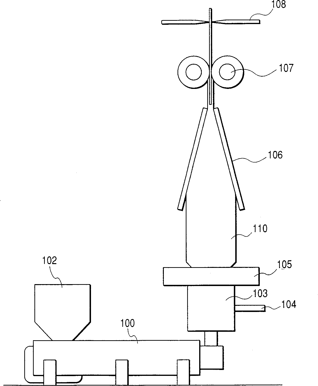
[0118] 2. Next, in image 3 In the extrusion device shown, the die head 103 of the extruder is set as a single-layer circular die, and the outer diameter of the die slit is 100mm. The width of the die seam was 0.8 mm. The above extruded material a' heated and dried well is put into the hopper 102 of the extruder, and then heated and melted. The molten product was extruded from the circular die 103 at 210°C. An outer cooling ring 105 surrounds the circular die 103 and air from the atmosphere is blown into the fil...

example 1-2

[0132] (1) Manufacture of intermediate transfer belt 5:

[0133] Two kinds of intermediate transfer belts 5 were manufactured in the same manner as in Example 1-1 except that the recipe was changed to the following recipe b.

[0134] Formulation b: (by weight)

[0135] 100 parts of polyvinylidene chloride resin (PVDF)

[0136] Conductive carbon black 8 parts

[0137] (2) Manufacture of the latent image bearing member 1:

[0138] As the latent image bearing member 1, the same latent image bearing member 1 as in Example 1-1 was used.

[0139] (3) Measurement of physical properties and image printing test

[0140] On the intermediate transfer belt 5, physical properties were measured and an image printing test was performed in the same manner as in Example 1-1. Therefore, when the intermediate transfer belt 5 and the latent image bearing member 1 are rubbed against each other, the surface potential Vt of the latent image bearing member 1 is +180V.

[0141] The surface rough...

example 1-3

[0144] 1) Manufacture of intermediate transfer belt 5:

[0145] Two kinds of intermediate transfer belts 5 were manufactured in the same manner as in Example 1-1 except that the recipe was changed to the following recipe c and both the kneading temperature and the extrusion temperature were set to 220°C.

[0146] Formulation c: (by weight)

[0147] Amorphous polyamide resin 100 parts

[0148] 20 parts of polyether ester amide resin

[0149] (2) Manufacture of the latent image bearing member 1:

[0150] As the latent image bearing member 1, the same latent image bearing member 1 as in Example 1-1 was used.

[0151] (3) Measurement of physical properties and image printing test

[0152] On the intermediate transfer belt 5, physical properties were measured and an image printing test was performed in the same manner as in Example 1-1. Therefore, when the intermediate transfer belt 5 and the latent image bearing member 1 are rubbed against each other, the surface potential Vt...


PUM


Abstract

A process cartridge integrally supporting therein a cylindrical latent image bearing member on which a toner image is formed and an intermediate transfer belt which is first transferred to the intermediate transfer belt belt, and then transferred from the intermediate transfer belt to the transfer medium for the second time. In order to prevent undesired triboelectric charging of the photosensitive member during transportation, the process cartridge shall meet any one of the following requirements, A) When the intermediate transfer belt and the photosensitive member are rubbed against each other, the surface potential Vt of the latent image bearing member -200V≤Vt≤200V, B) A spacer is provided between the intermediate transfer belt and the latent image bearing element, when the former and the latter rub against each other, the surface potential Vt of the photosensitive element is -200V≤Vt≤200V, And C) the process cartridge has a means for reducing the contact pressure of the intermediate transfer belt against the latent image bearing member.

Description

field of invention [0001] The present invention relates to a process cartridge having a latent image bearing member having a toner image formed on its surface and an integrally disposed intermediate transfer zone. Background technique [0002] An image forming device utilizing an intermediate transfer belt of a belt-shaped intermediate transfer member can be effectively used as a full-color image forming device and a multicolor image forming device in which multiple color toner images are successively and superimposedly transferred onto a transfer medium to output an imaged material. [0003] Compared with the transfer system disclosed in Japanese Patent Application Laid-Open Sho 63-301960, this transfer system is an image forming apparatus in which a toner image is transferred from an electrophotographic photosensitive member as a first image bearing member onto the transfer medium as the second image bearing member, and then attached or attracted to the transfer drum, the...

Claims


Application Information

Patent Timeline
Patent Type & Authority Applications(China)
IPC IPC(8): G03G15/16G03G21/18
CPCG03G21/181G03G2215/0177G03G15/16
Inventor 草场隆小林广行仲泽明彦田中笃志芦边恒德松田秀和
Owner CANON KK
Why Eureka
Try Eureka