High-speed plastic circular loom without shuttle roller track

A circular loom and track technology, applied in circular looms, looms, textiles, etc., can solve the problems of low speed and limit the speed of plastic circular looms, and achieve the effect of increasing the speed

A circular loom and track technology, applied in circular looms, looms, textiles, etc., can solve the problems of low speed and limit the speed of plastic circular looms, and achieve the effect of increasing the speed

CN1379134AInactive Publication Date: 2002-11-13黄美昌

Image

  • High-speed plastic circular loom without shuttle roller track
  • High-speed plastic circular loom without shuttle roller track
  • High-speed plastic circular loom without shuttle roller track

Examples


Embodiment Construction

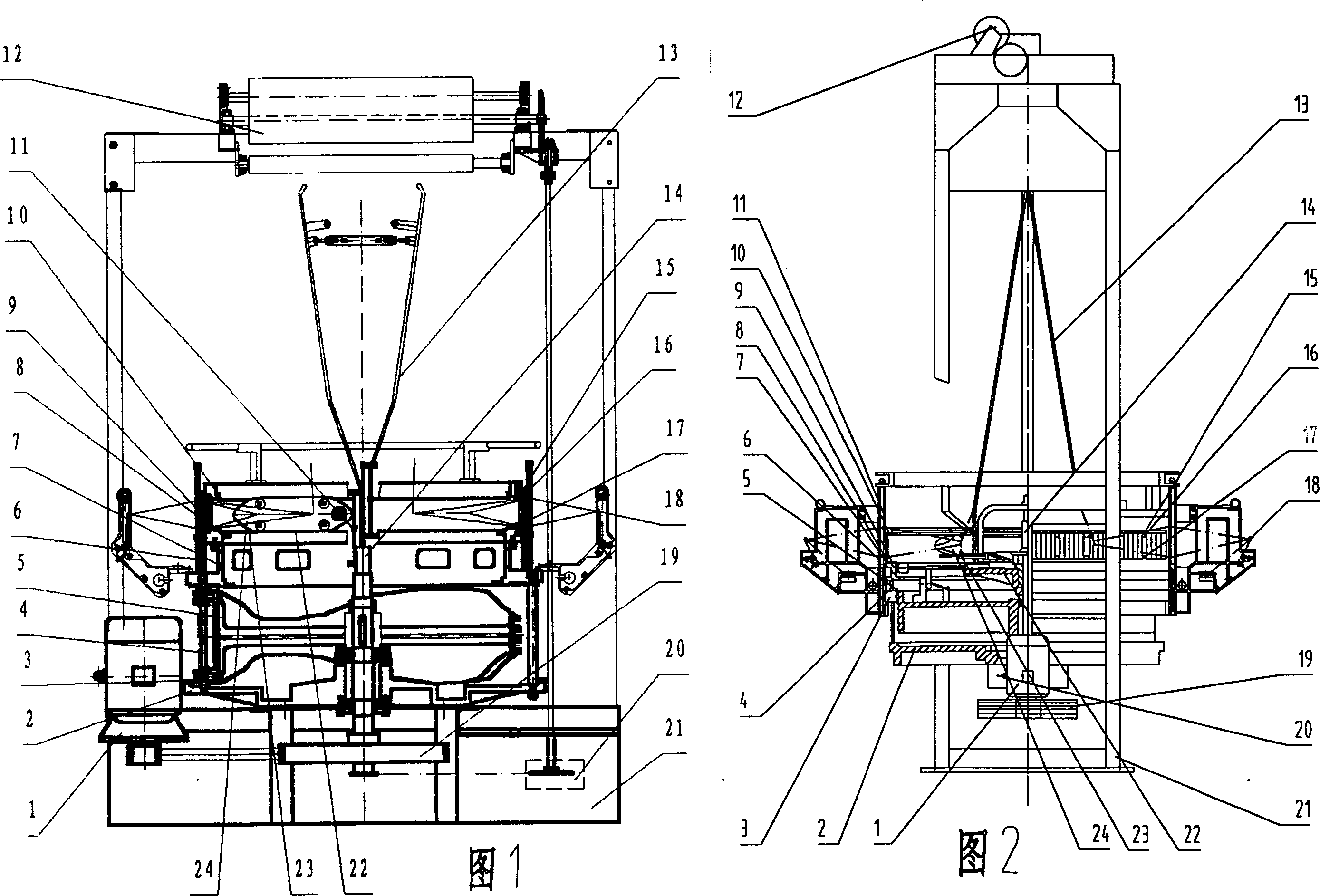
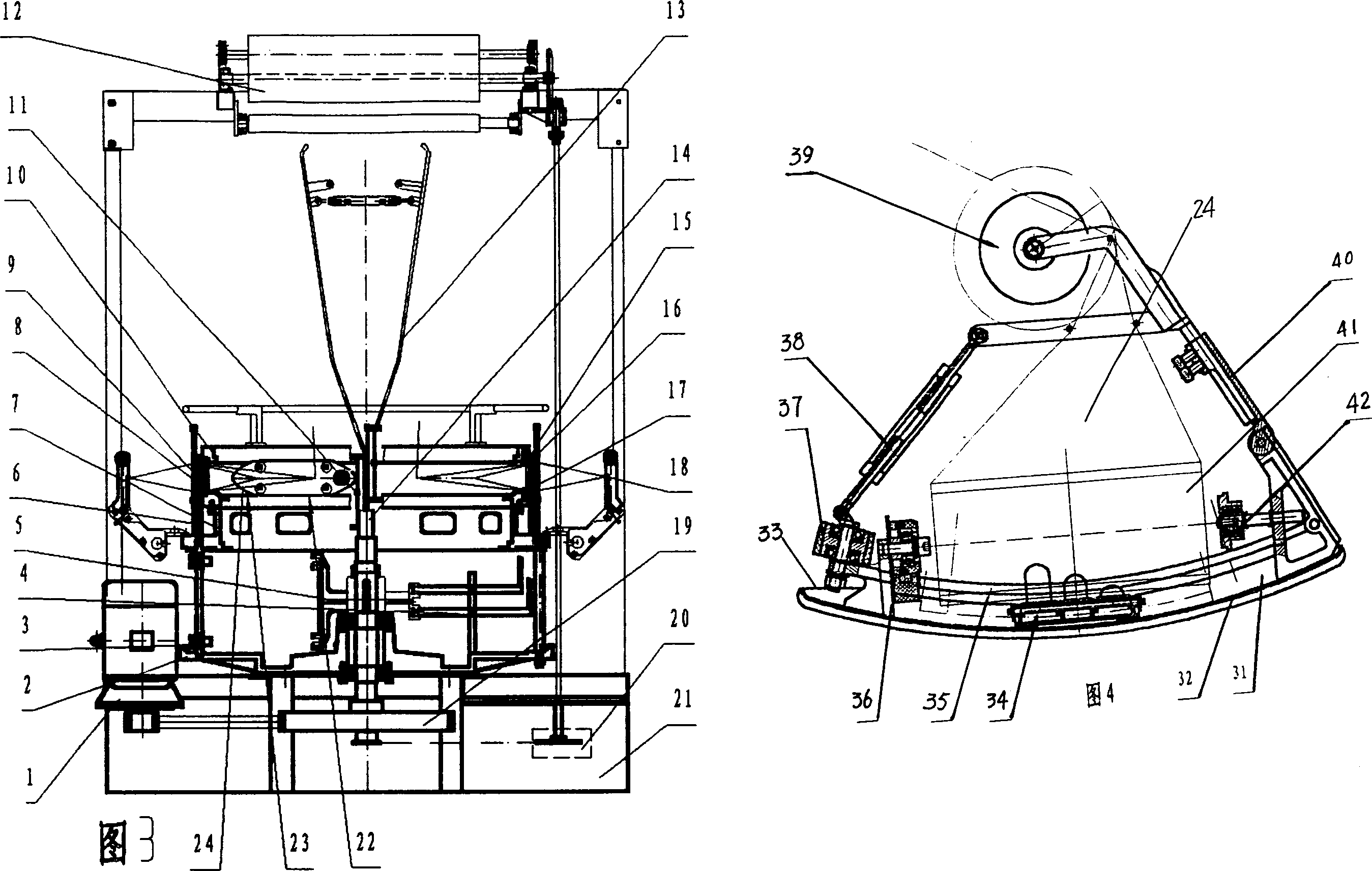
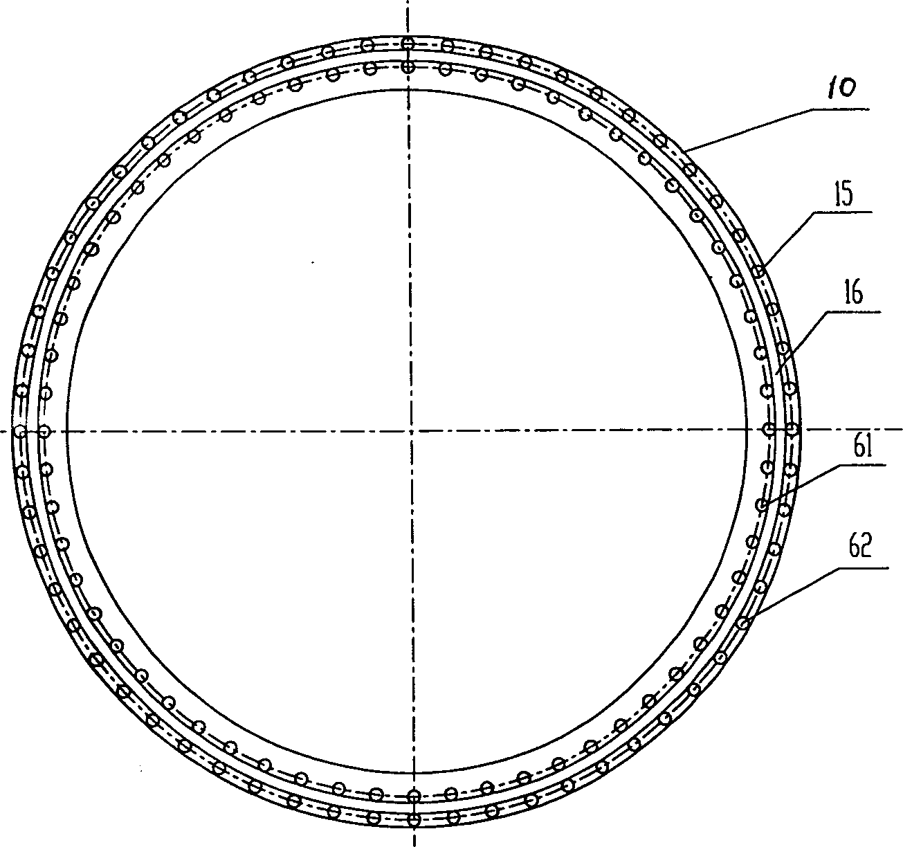
[0025] Referring to Figure 1, Figure 2, Figure 3, the main engine of the present invention is composed of a motor (1), a chassis (2), a slider (3), a slider guide column (4) or a connecting rod (4), a cam (5) or a small Cam (5), slide bar (6) or brown belt (6), middle ring (7), buckle door (8), lower door ring (9), upper door ring (10), brown frame (11) or brown wire (11), lifting device (12), expander (13), main shaft (14), jumper (18), drive belt (19), speed change mechanism (20), chassis (21), turntable (22) , Shuttle thruster (23), shuttle (24) and electrical control device. The basic structures in Figure 1, Figure 2, and Figure 3 are the same. The difference in individual components is that the slider (6) and the brown frame (11) in Figure 1 are the brown belt (6) and the brown wire (11) in Figure 2 , And comparing Figure 1 with Figure 3, the slider guide post (4) and cam (5) in Figure 1 are the connecting rod (4) and the small cam (5) in Figure 3, and the rest of the compone...


PUM


Abstract

A high-speed circular loom for weaving plastic bags (or cloth) technically features that on the basis of original plastic circular loom structure, 30-432 roller units installed to upper ring and 30-432 roller units installed to lower ring constitute respectively the upper and the lower tracks, and the shuttle carries has two convex arc ribs matched with the rollers on the upper and the lower tracks, so eliminating the squeeze and shear forces of shuttle roller to thread and reaching high speed.

Description

Technical field [0001] The invention relates to a textile machine, which is a production equipment for plastic woven bags (cloth), in particular a high-speed plastic circular loom without a shuttle wheel rolling track. Background technique [0002] At present, the plastic circular looms used in the production of plastic woven bags (cloth) in various countries in the world are divided into 4 shuttles, 6 shuttles, small 6 shuttles, 8 shuttles, and 12 shuttles according to the number of shuttles; according to the structure, they are divided into brown belt type. , Brown frame type, small cam link type circular loom. The basic structure of the main machine consists of a motor (1), a chassis (2), a slider (3), a slider guide column or connecting rod (4), a cam or a small cam (5), a slider or brown belt (6), a middle Ring (7), button door (8), lower door ring (9), upper door ring (10), brown frame or brown wire (11), lifting device (12), expander (13), spindle (14) , Jumper (18), trans...

Claims


Application Information

Patent Timeline
13 Nov 2002
Publication
CN1379134A
IPC
D03D37/00; D04C3/40
Inventors
黄美昌