Supercharge Your Innovation With Domain-Expert AI Agents!

Voltage detecting circuit

A voltage detection circuit and a detection circuit technology are applied in the field of voltage circuits, which can solve the problems of low response speed of comparators and inability to detect sharp changes in voltage.

Inactive Publication Date: 2002-11-13
SII SEMICONDUCTOR CORP
View PDF0 Cites 11 Cited by
  • Summary
  • Abstract
  • Description
  • Claims
  • Application Information

AI Technical Summary

Problems solved by technology

[0008] However, when current consumption is reduced in a conventional voltage detection circuit, there is a problem that the response speed of the comparator in the voltage detection circuit becomes low, and as a result, a sudden change in voltage cannot be detected

Method used


Image

  • Voltage detecting circuit
  • Voltage detecting circuit
  • Voltage detecting circuit

Examples


no. 2 example

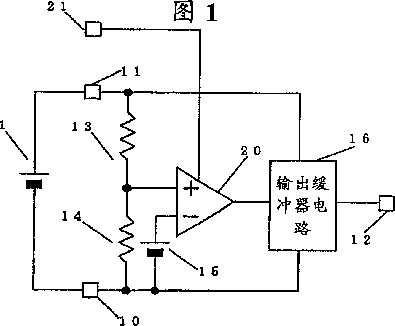
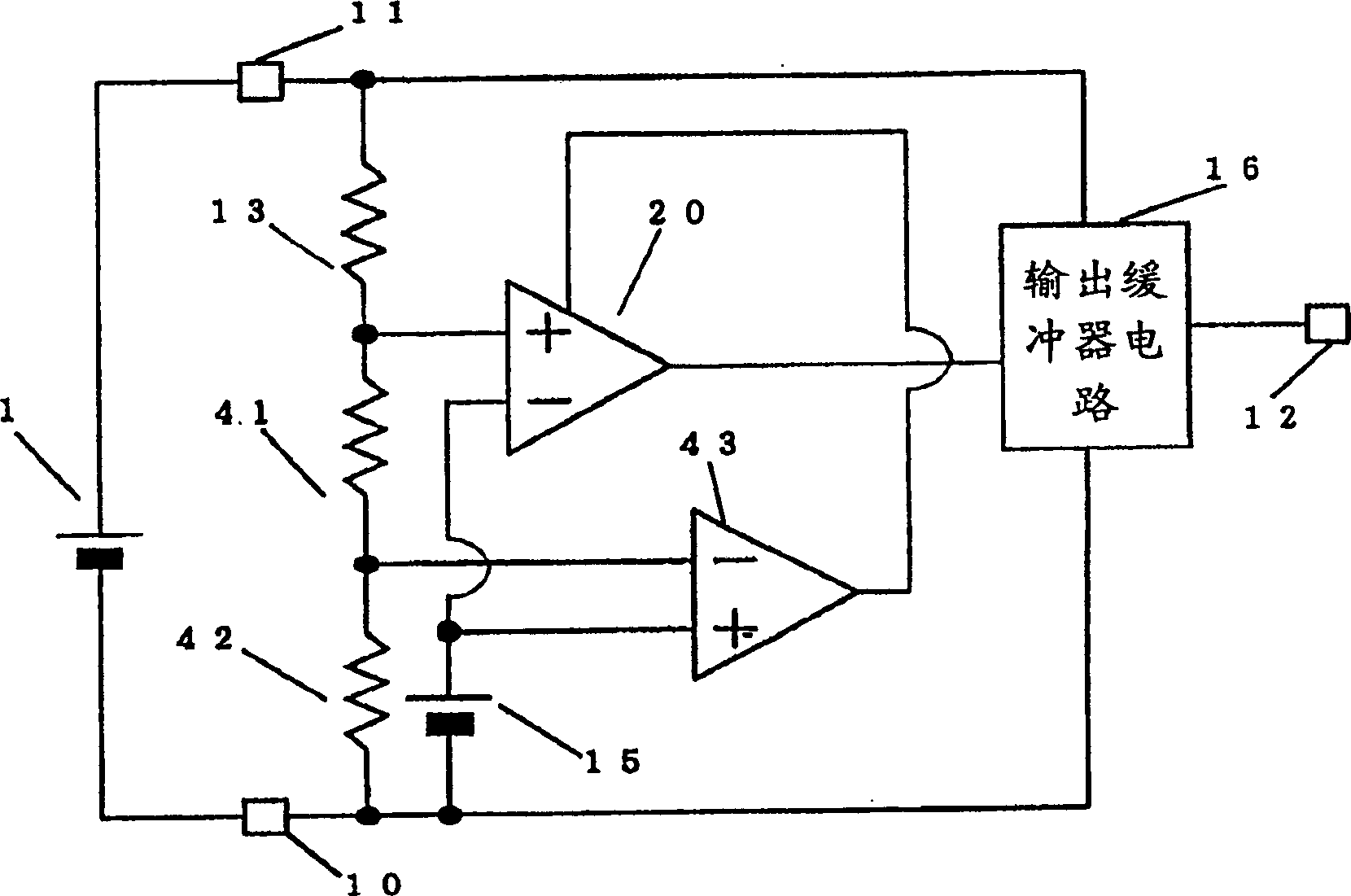
[0026] image 3 is a schematic diagram showing a voltage detection circuit according to a second embodiment of the present invention. image 3 The difference between the shown voltage detection circuit and the circuit in Fig. 1 is that the voltage dividing resistor 14 is replaced by voltage dividing resistors 41 and 42, and a comparator 43 is added to control the current of the comparator 20 according to the output of the comparator 43 value. Therefore, the function of the terminal 21 shown in FIG. 1 is replaced by the output of the comparator 43 . Assuming that the resistance values ​​of the resistors 41 and 42 are R3 and R4 respectively, in order to obtain the same detection voltage as in FIG. 1, according to expression (1), R3+R4=R2 must be satisfied. Also, as in the expression (1), the voltage to invert the output of the comparator 43 is represented by the following expression (2):

[0027] Reverse voltage = (R1+R3+R4) / R4×Vb ...(2)

[0028] That is, when the voltage is...


PUM


Abstract

A voltage detection circuit that controls the current consumption of the circuit to detect voltage at high speed while suppressing battery consumption.

Description

technical field [0001] The present invention relates to a circuit for detecting voltage in an integrated circuit contained in a battery-operated portable device. technical background [0002] As for the voltage detection circuit, a circuit as shown in the circuit block diagram of FIG. 6 is known. That is, terminals 10 and 11 are connected to any terminal to be detected. In the example of FIG. 6, since the battery 1 is connected to the terminals 11 and 10, the voltage across the battery 1 is detected. Voltage dividing resistors 13 and 14 are connected between terminals 11 and 10 . The input end of the comparator 17 is connected to the junction of the voltage dividing resistors 13 and 14 and the reference voltage 15 . The output terminal of the comparator 17 is connected to the output buffer circuit 16 , and the output terminal of the output buffer circuit 16 is connected to the output terminal 12 . [0003] The voltage is detected by comparing the voltage Va at the juncti...

Claims


Application Information

Patent Timeline
IPC IPC(8): G01R19/00G01R19/165G05F1/10
CPCG01R19/16542G01R19/00
Inventor 须藤稔
Owner SII SEMICONDUCTOR CORP
Features
  • R&D
  • Intellectual Property
  • Life Sciences
  • Materials
  • Tech Scout
  • Unparalleled Data Quality
  • Higher Quality Content
  • 60% Fewer Hallucinations
Learn More