Deformation analyzer of barrel body
A technology of measuring device and cylindrical body, which is applied to measuring devices, optical devices, bearings for rotating motion, etc., can solve the problems of large measuring errors, inability to perform stability and reliability, time-consuming and troublesome, etc.
- Summary
- Abstract
- Description
- Claims
- Application Information
AI Technical Summary
Problems solved by technology
Method used
Image

Examples
Embodiment Construction
[0019] Preferred embodiments of the present invention will be described in detail below with reference to the accompanying drawings. The accompanying drawings do not limit the present invention, but are intended to make the present invention easy to understand. In addition, detailed descriptions of well-known parts are omitted in order not to obscure the invention.
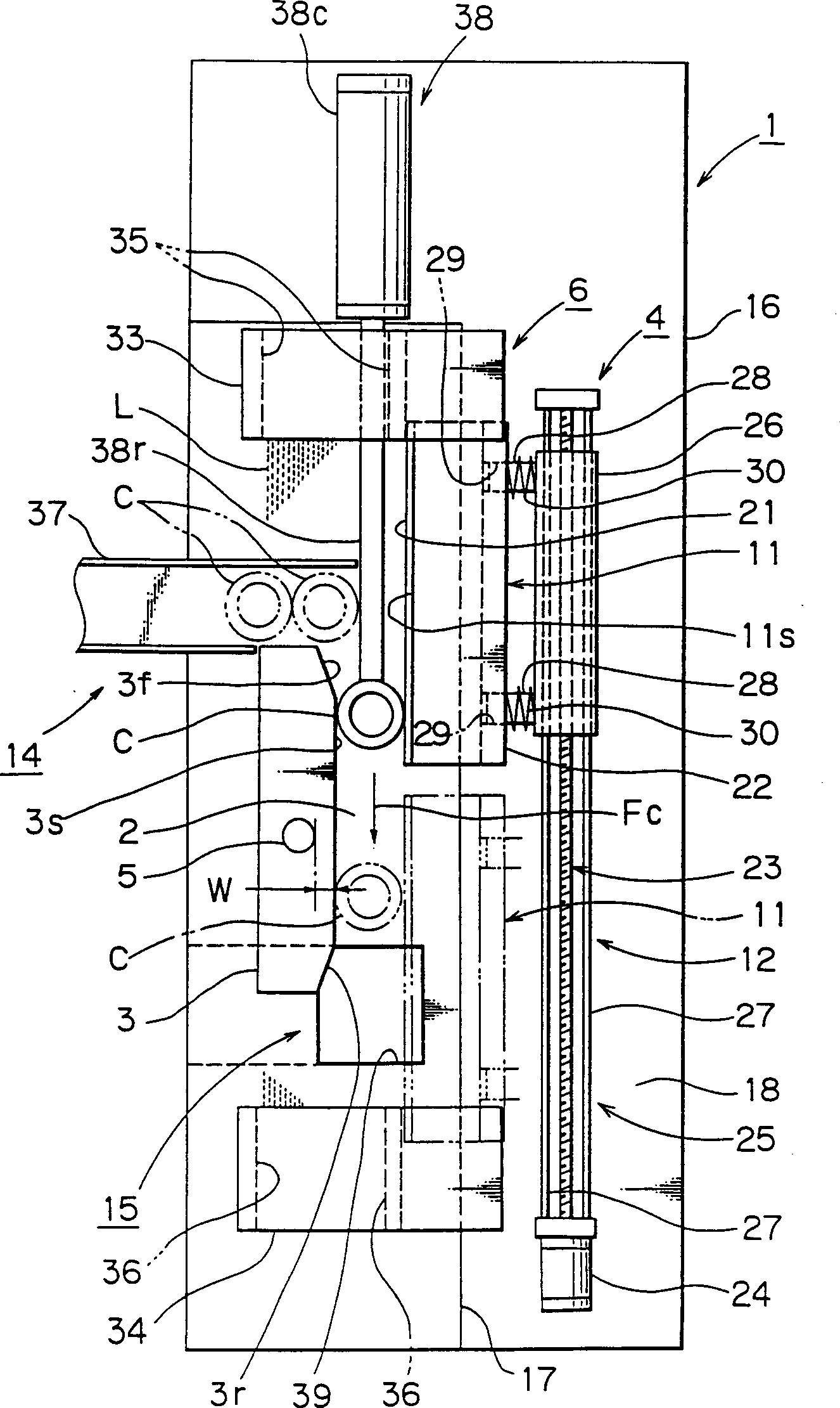
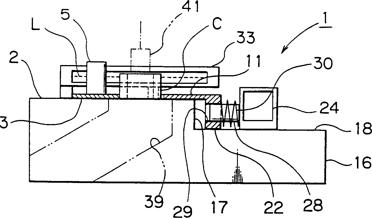
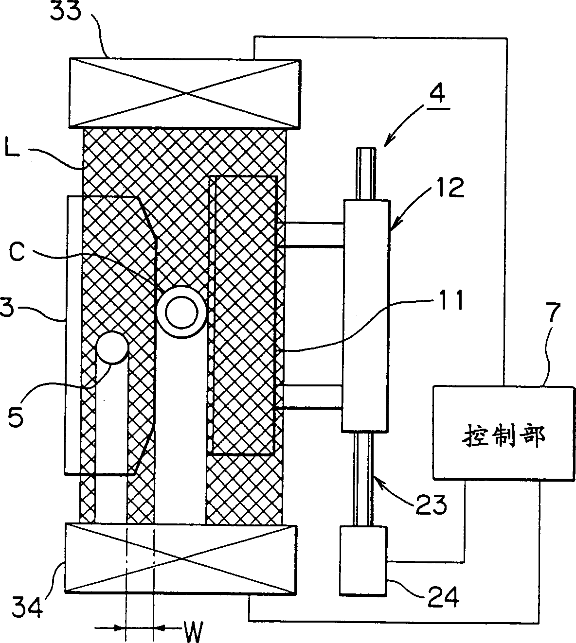
[0020] First, refer to Figure 1-Figure 4 The configuration of the strain measuring device 1 of this embodiment will be described.
[0021] In the figure, symbol 16 is a base on which a flat surface 2 is formed. At the middle position of the flat surface 2, a fixed linear guide part 3 is fixedly provided. The fixed linear guide part 3 is formed of a guide member having a certain thickness, and at least one side is formed with a linear side part 3s having a length such that the cylindrical body C as the object to be measured can be turned more than one turn. The linear side portion 3s ensures a high degree of l...
PUM
 Abstract
Description
Claims
Application Information
 - R&D
- Intellectual Property
- Life Sciences
- Materials
- Tech Scout
- Unparalleled Data Quality
- Higher Quality Content
- 60% Fewer Hallucinations
Browse by: Latest US Patents, China's latest patents, Technical Efficacy Thesaurus, Application Domain, Technology Topic, Popular Technical Reports.
© 2025 PatSnap. All rights reserved.Legal|Privacy policy|Modern Slavery Act Transparency Statement|Sitemap|About US| Contact US: help@patsnap.com