Acoustic wave device comprising alternating polarisation domains

A technology of acoustic wave devices and polarized regions, applied in electrical components, impedance networks, etc., to solve problems such as electrode short-circuits

Inactive Publication Date: 2002-12-18
THALES SA
View PDF0 Cites 0 Cited by
  • Summary
  • Abstract
  • Description
  • Claims
  • Application Information

AI Technical Summary

Problems solved by technology

[0005] Moreover, when electrodes that are closely spaced apart are energized, the constituent metals of said electrodes, in this case aluminum (the most use...

Method used


Image

  • Acoustic wave device comprising alternating polarisation domains
  • Acoustic wave device comprising alternating polarisation domains
  • Acoustic wave device comprising alternating polarisation domains

Examples


Embodiment Construction

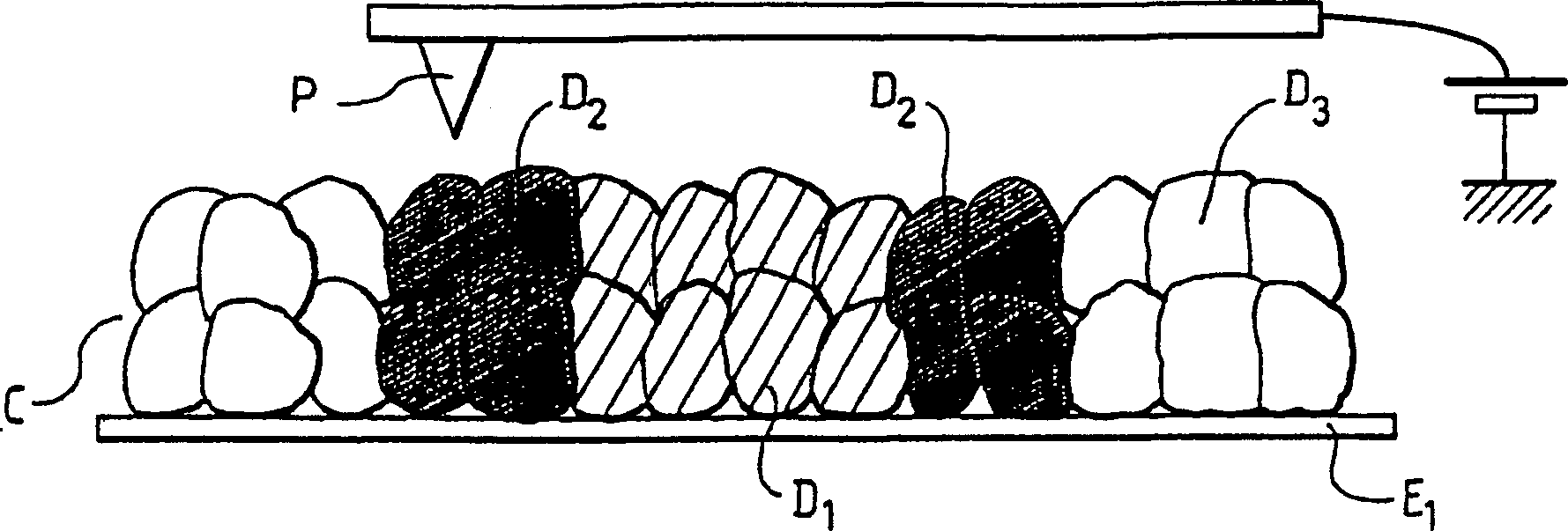
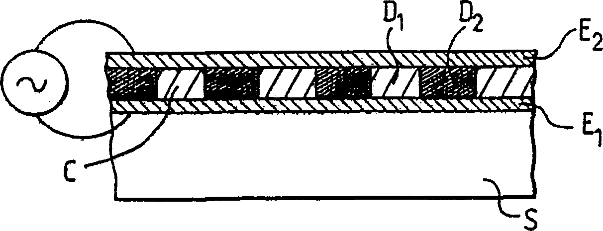
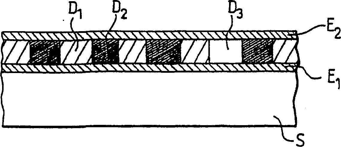
[0021] In summary, the present invention provides an acoustic wave device employing a layer of ferroelectric material in which regions of alternating polarization are formed.

[0022] In particular, the present invention proposes to generate regions of localized polarization and to derive advantages from such localized polarizations in order to functionalize or periodize the electroacoustic properties of the formed material in order to produce acoustic wave devices which, due to the local electric polarization, rely on Piezoelectrically actuate ferroelectric materials on any type of metal substrate or metallized surface.

[0023] For this purpose, a layer of ferroelectric material is formed in conventional manner on the surface of the metal substrate or on the surface of the metallized substrate. In general, this can be any single or polycrystalline ferroelectric material, for example, lead titanium zirconium oxide (PZT), LiNbO 3 , LiTaO 3 or KNbO 3 . Typically, the thickn...


PUM


Abstract

The invention relates to an acoustic wave device comprising a ferroelectric material layer (C) and a substrate (S). A layer of ferroelectric material is located between a first electrode (E1) and a second electrode (E2) deposited on the surface of the substrate or is an integral part of the substrate, the layer of ferroelectric material comprising a positive first polarization region ( D1) and a negative second polarization region (D2). For the field of surface wave sensors, the structure can preferably be made into conversion regions with pitches on the order of hundreds of nanometers, so as to be suitable for high-frequency (on the order of one gigahertz) applications.

Description

technical field [0001] The present invention relates to acoustic wave devices, and more particularly to surface wave sensors capable of operating at very high frequencies on the order of several gigahertz. Background technique [0002] Typically, currently manufactured sensors use a comb-like structure based on interdigitated electrodes, using two, four or eight electrodes for each wavelength λ, where λ corresponds to the central operating frequency of the sensor, depending on the application needs. In various sensors, the ratio of the area of ​​the metallized surface on the substrate to the area of ​​the free surface is generally used in the range of about 0.25 to 0.75. [0003] However, a new type of sensor has emerged, the so-called small-gap sensor, in which the free surface is very small in order to obtain the smallest possible distance between two adjacent electrodes. The advantage of this type of sensor is that the largest possible electrode width per cycle can be ob...

Claims


Application Information

Patent Timeline
IPC IPC(8): H03H3/08H03H9/02H03H9/145
CPCH03H9/02574H03H9/145H03H9/14505H03H9/178
Inventor 西尔万·巴朗德拉布里塞·戈蒂埃达尼埃尔·豪德恩让-克洛德·拉布吕纳
Owner THALES SA
Why Eureka
Try Eureka