Oscillation preventing circuit

A circuit and control circuit technology, applied in the direction of transducer circuit, electrical components, transducer acoustic response prevention, etc., can solve the problem of small gain of communication equipment

Inactive Publication Date: 2002-12-25
FUKUOKA INSTITUTE OF TECHNOLOGY +1
View PDF0 Cites 2 Cited by
  • Summary
  • Abstract
  • Description
  • Claims
  • Application Information

AI Technical Summary

Problems solved by technology

This oscillation phenomenon occurs because the loop gain in the electrical connection containing sound wave propagation is greater than 1, and in order to ensure that the loop gain is never greater than 1, corresponding countermeasures should be taken, such as keeping the sound collection unit such as the microphone far away from the A microphone amplifie...

Method used


Image

  • Oscillation preventing circuit
  • Oscillation preventing circuit
  • Oscillation preventing circuit

Examples


Embodiment Construction

[0020] Specific ways of implementing the invention

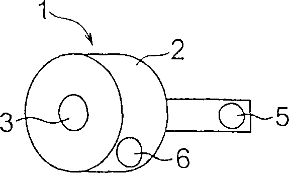
[0021] A first embodiment of the present invention will be described below with reference to the drawings. In a first embodiment, the present invention is applied to a microphone amplifier to amplify weak audio signals and to amplify sound using a speaker. This microphone amplifier is typically used in environments such as figure 1 shown, and in figure 1 Among them, denoted by reference numeral 1 is a microphone amplifier, which is partially or completely inserted into the user's ear like a hearing aid when in use, and this microphone amplifier has a cylindrical body 2 with a central part of one end face Microphone 3 for collecting weak speech and sound, and on the opposite side there is also a small-diameter speaker 5 protruding from the central part of the back. Reference numeral 6 denotes a battery.

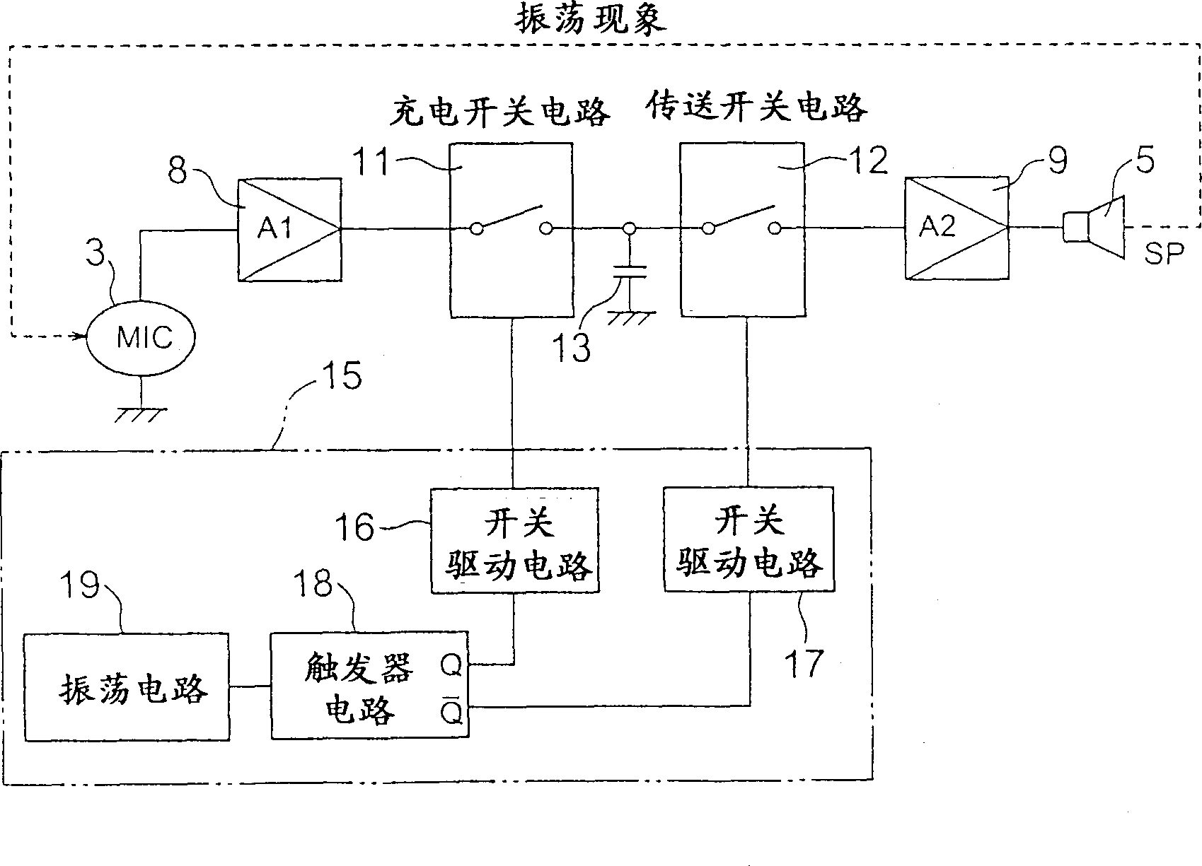
[0022] figure 2 To show a block diagram of the oscillation prevention circuit and other related parts in the microph...


PUM


Abstract

The oscillation prevention circuit is characterized in that a charge switch circuit and a transmission switch circuit are connected in series between the first amplifier circuit and the second amplifier circuit; The switch circuit is turned "off", and the charging switch circuit is turned "off" when the transfer switch circuit is "on", so as to prevent both switch circuits from being turned "on" at the same time.

Description

technical field [0001] The present invention relates to an oscillation preventing circuit, which can be applied to microphone amplifiers for one-way communication (such as hearing aids); microphone amplifiers for deaf-mute or damaged vocal cords; communication equipment for travel guides; loudspeakers; equipment; communication equipment for train attendants; and headsets for operators; and transceivers for interactive communications, such as microphone amplifiers for headsets; slave devices for mobile communications (such as mobile phones); general-purpose telephones; and These devices and tools are oscillating converters. Background technique [0002] In the usual technology, when trying to collect speech and sound by means of a microphone and amplify the speech and sound by using a speaker or earphone through an amplifying circuit, an oscillation phenomenon sometimes occurs because of the sound wave transmission including the sound collecting unit and the sound amplifying ...

Claims


Application Information

Patent Timeline
IPC IPC(8): H04B3/20H04R3/02H04R25/00
CPCH04R3/02H04R25/453H04B3/20
Inventor 濑户信次谷口泰敏
Owner FUKUOKA INSTITUTE OF TECHNOLOGY
Why Eureka
Try Eureka