
High linear balanced amplifier with asymmetric biassed voltages

A technology of amplifiers and peak amplifiers, applied in the direction of amplifiers, amplifier combinations, and amplifiers with distributed constants in the coupling network, which can solve the problems of complex power amplifiers, low efficiency, and linearity

Inactive Publication Date: 2003-01-15
TRW INC
View PDF15 Cites 1 Cited by
  • Summary
  • Abstract
  • Description
  • Claims
  • Application Information

AI Technical Summary

Problems solved by technology

First, the carrier amplifier only operates at half of its maximum power capability, which results in lower efficiency and linearity
Second, the power amplifier is relatively complex, including multiple phase-shifting elements

Method used


Image

  • High linear balanced amplifier with asymmetric biassed voltages
  • High linear balanced amplifier with asymmetric biassed voltages
  • High linear balanced amplifier with asymmetric biassed voltages

Examples


Embodiment Construction

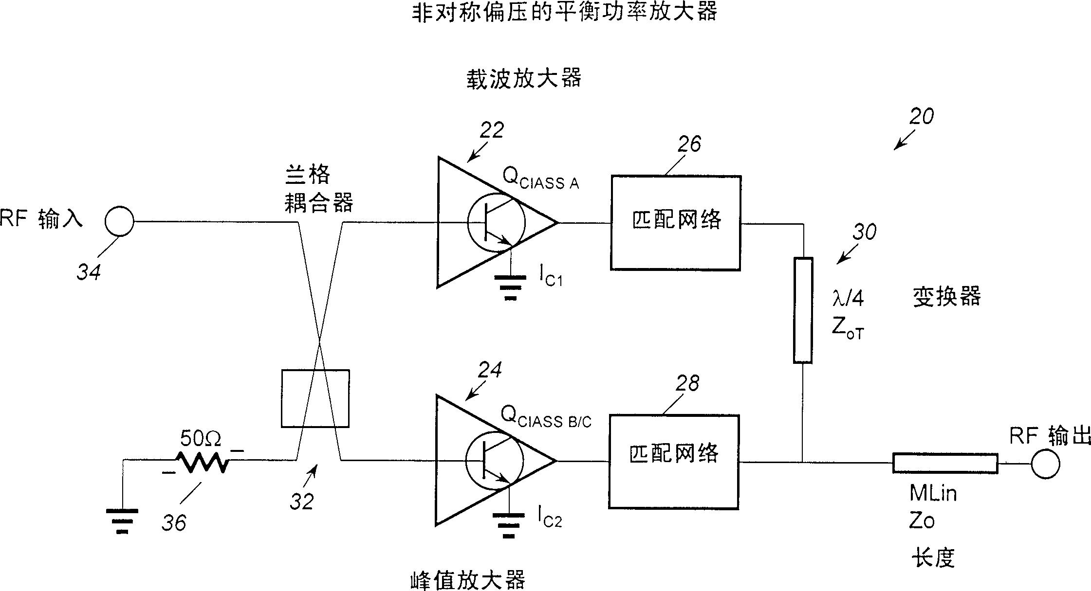
[0015] The present invention relates to a microwave power amplifier, indicated generally at 20, configured as a Doherty amplifier. The microwave power amplifier 20 includes a carrier amplifier 22 and a peak amplifier 24 . The carrier amplifier 22 and the peaking amplifier can be formed from heterojunction bipolar transistors (HBT) 22 and specifically as pre-matched 1.5*30μm 2 *4 refers to a DHBT device with a total emitter area of ​​180 μm 2 . An example of such a device is in "18-21GHzInP DHBT Linear Microwave Doherty Amplifier" by Kobayashi et al., 2000 IEEE Radio Frequency Integrated Circuits abstract pp. 179-182 of , which are hereby incorporated by reference. Methods of making HBT are well known in the art, such as disclosed in commonly owned U.S. Patent Nos. 5,162,243, 5,262,335, 5,352,911, 5,448,087, 5,672,522, 5,648,666, 5,631,477, 5,736,417, 5,804,487, 5,994,194, which are incorporated herein by reference

[0016] In order to bring the output signals of the car...


PUM


Abstract

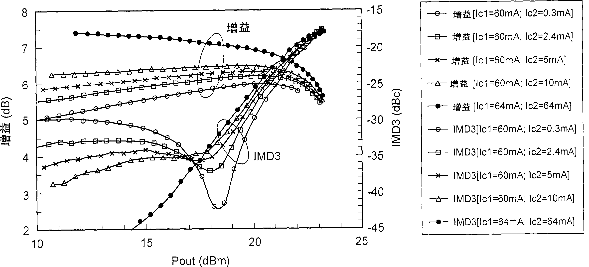
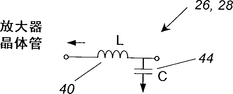
The patent relates to asymmetrically biased high linerrity balanced amplifier,and more particularly to a microwave amplifier configured as a Doherty amplifier. In particular, the amplifier includes a carrier amplifier, a peak amplifier, a Lange coupler at the input of the amplifiers and quarter wave amplifier at the output of the amplifiers. In order to improve isolation between the amplifiers to minimize the dependence of each amplifier's inter-modulation (IM) performance on the others, matching networks are provided, coupled to the output of the amplifiers. In addition, the microwave power amplifier includes electronic tuning which allows for improved inter-modulation distortion over a wide input power dynamic range, which allows the IM performance of the microwave amplifier to be adjusted for the operating frequency of the amplifier.

Description

[0001] Cross References to Related Applications [0002] This application is related to a publicly owned pending patent application: Kevin Kobayashi, Application No. XXX, "HEMT-HBT Doherty Microwave Amplifier," filed concurrently with this application, Attorney Docket No. 12-1107, and Kevin W . Kobayashi, Application No. XXX, "Using Doherty as a Predistortion Circuit for Linearizing Microwave Amplifiers," filed concurrently with this application, Attorney Docket No. 12-1101. technical field [0003] The present invention relates to a power amplifier, and more particularly to a microwave power amplifier topology, which provides high output power with excellent phase and amplitude linearity over a relatively wide frequency range and at relatively high output power levels. Background technique [0004] RF and microwave communication systems place increasing demands on the linearity and efficiency of power amplifiers. Unfortunately, conventional power amplifiers operate at opti...

Claims


Application Information

Patent Timeline
IPC IPC(8): H03F3/60H03F1/02H03F1/07H03F3/68
CPCH03F1/0288H03F1/07
Inventor 凯文·W·科巴亚西
Owner TRW INC
Learn More