Spinning plate used in non-woven fabric production

A technology of non-woven fabrics and spinnerets, applied in textiles and papermaking, spinneret assemblies, melt spinning, etc., can solve problems such as rough surface of spinneret fibers and lower spinneret efficiency

Inactive Publication Date: 2003-01-22
SUETOMI ENG
View PDF1 Cites 7 Cited by
  • Summary
  • Abstract
  • Description
  • Claims
  • Application Information

AI Technical Summary

Problems solved by technology

However, there is such a problem that the cold air that suddenly blows out directly below the discharge end of the cold air discharge port forms a vortex, thereby forming roughness on the surface of the spinning fiber.
The latter is sometimes stuck at the nozzle, thereby reducing the spinning efficiency

Method used


Image

  • Spinning plate used in non-woven fabric production
  • Spinning plate used in non-woven fabric production
  • Spinning plate used in non-woven fabric production

Examples


Embodiment Construction

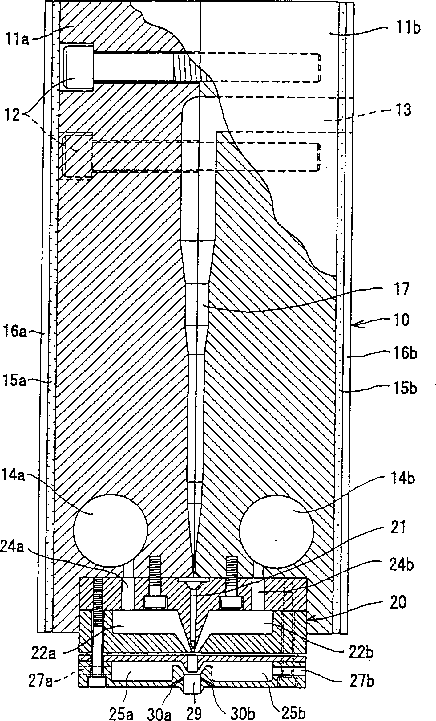
[0013] The following will refer to Figures 1 to 4 A preferred embodiment of the present invention is described. As shown, the spinneret 20 is installed at the bottom of the spinneret 10, wherein the two main bodies 11a and 11b of the spinneret are bolted together. An injection port 13 is provided at the upper portion of the main bodies 11a, 11b for supplying molten polymer such as polypropylene resin, polyester resin, or nylon (trademark). At the bottom of the main bodies 11a, 11b, hot air supply ports 14a, 14b are provided. The flat heaters 15a and 15b are adjacent to the side surfaces of the main bodies 11a, 11b through the press plates 16a, 16b.

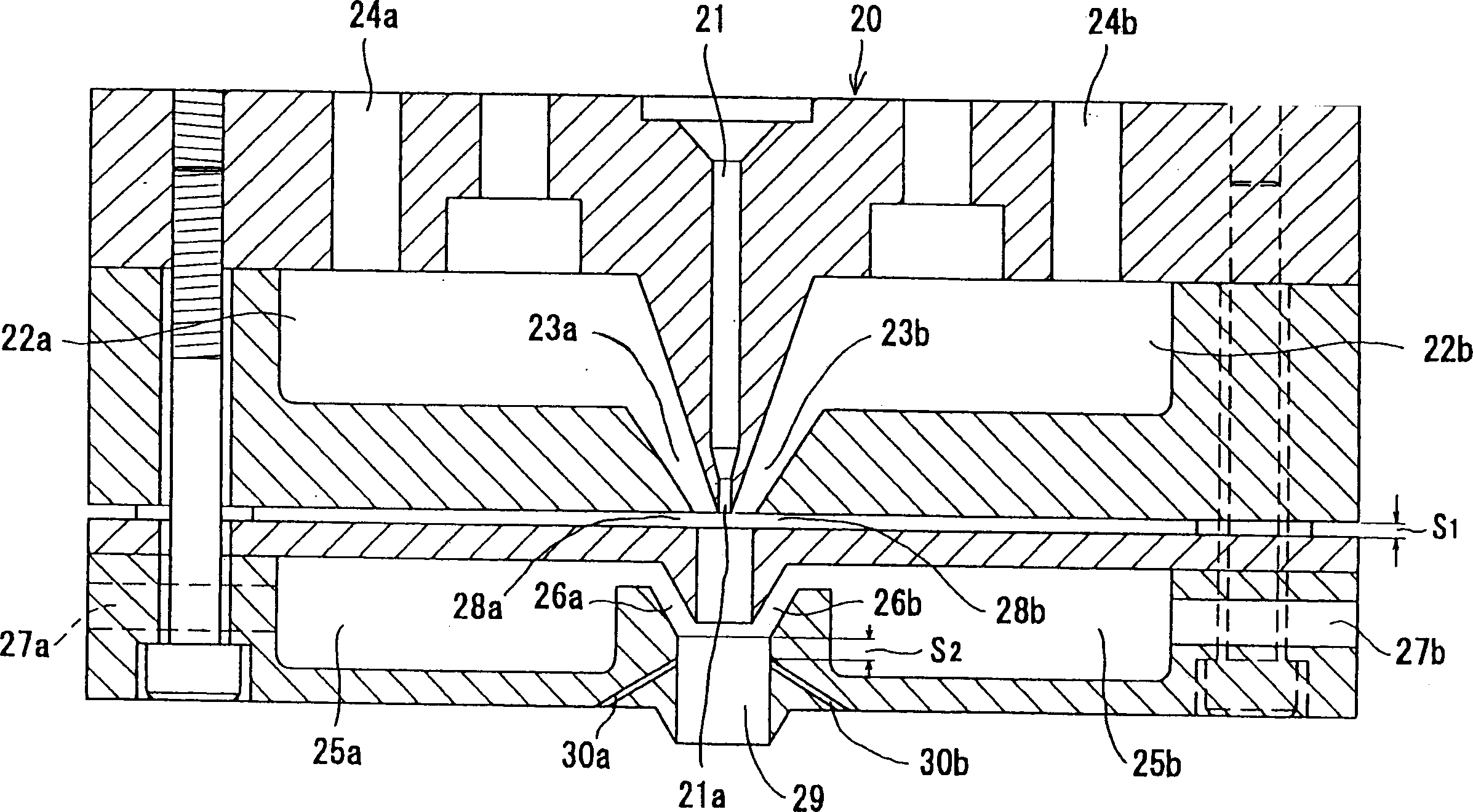
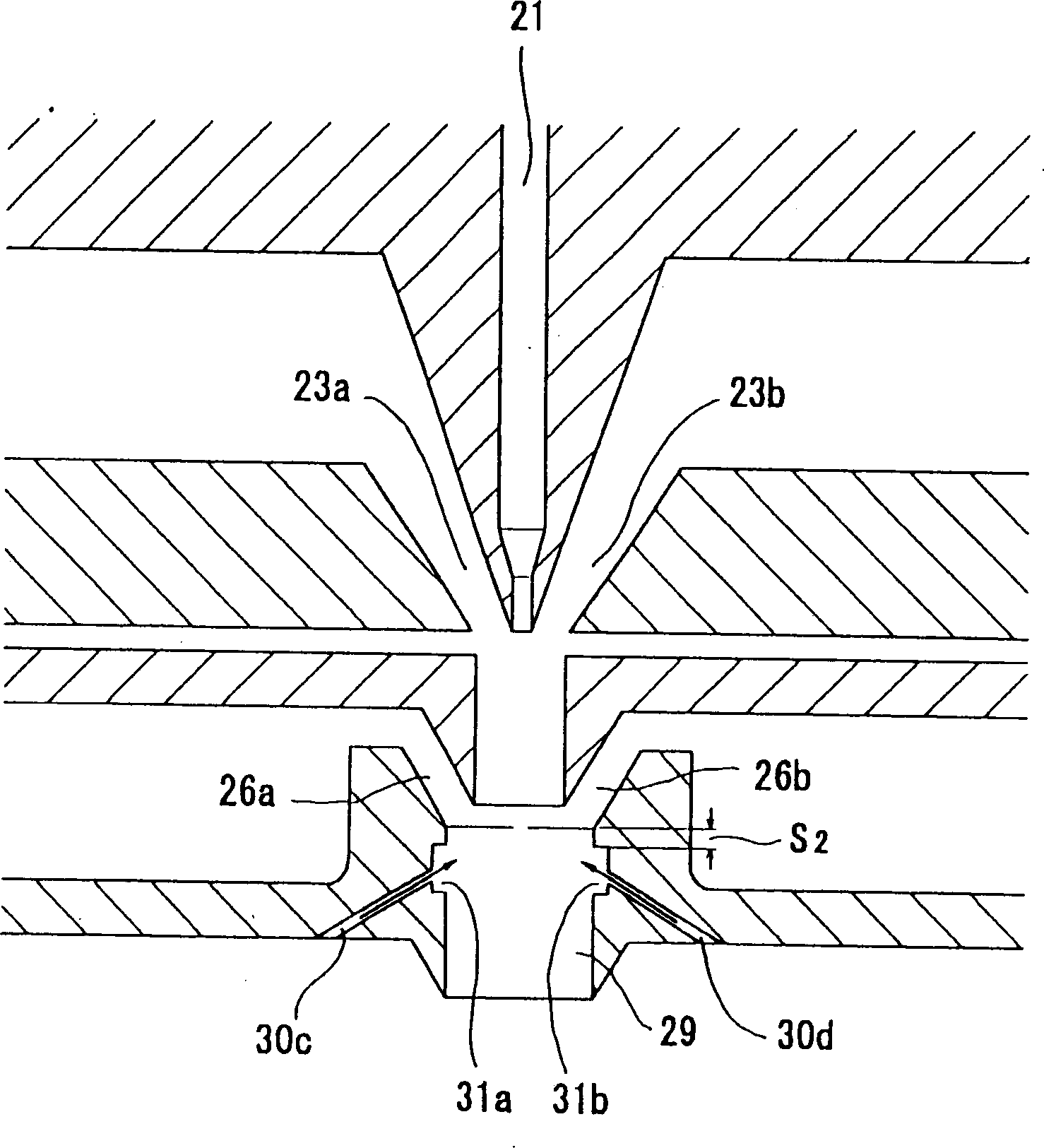
[0014] In the spinneret 20 , a plurality of nozzles 21 are arranged in a row at the tip of the polymer channel 17 communicating with the polymer injection port 13 . The tip 21a of the nozzle 21 is arranged between a pair of discharge openings or slots 23a and 23b which are used to discharge hot air from the hot air chambers 22...


PUM


Abstract

This present invention provides a spinning die for a melt-blow type nonwoven fabric, capable of spinning out a smooth fiber having a minute diameter, and capable of reducing an energy cost. This spinning die has a pair of hot air-jetting slits arranged at the vicinity of the tip of a nozzle for extruding a molten polymer, a pair of cold air-jetting slits arranged at the downstream thereof, and ventilation slits formed at the spinning opening. The pair of the slits are regulated so that a large amount of the cold air may be blown to draw the molten polymer extruded from the nozzle by the negative pressure. The ventilation slits reduce the whirlpool caused by the rapid jetting of the cold air to enable the fiber with the smooth surface to be spun.

Description

field of invention [0001] The invention relates to spinnerets for the production of nonwovens by the so-called meltblowing process. Background technique [0002] Such as Figure 5 As shown, in the melt blowing method, raw material sheets are put into a hopper 1, heated and melted in an extruder 2, and supplied to a die 3 for spinning. The short spun fibers are deposited onto a sheet on a conveyor belt 4 comprising a collection mesh. After the sheet passes through the calender rolls 5 while stripping the spun fibers from the conveyor belt 4, the spun fibers are crimped up by a crimping device 6 to produce a nonwoven fabric. [0003] The mold 3 ejects the molten resin discharged through the spinneret hole 3a by hot air supplied through the hot air discharge hole 3b. Because a precise balance is required between the amount of molten polymer discharged through the spinneret hole 3a and the amount of hot air, it is very difficult to eject fibers with a desired diameter, especia...

Claims


Application Information

Patent Timeline
Patent Type & Authority Applications(China)
IPC IPC(8): D01D5/08D01D4/02D04H3/16
Inventor 末富满
Owner SUETOMI ENG
Why Eureka
Try Eureka