Supercharge Your Innovation With Domain-Expert AI Agents!

Voltage comparing circuit

A voltage comparison circuit and reference voltage technology, applied in the direction of measuring current/voltage, multiple input and output pulse circuits, electrical components, etc., can solve the problem that the analog input signal and the reference voltage cannot be determined normally.

Inactive Publication Date: 2003-01-22
NEC ELECTRONICS CORP
View PDF1 Cites 3 Cited by
  • Summary
  • Abstract
  • Description
  • Claims
  • Application Information

AI Technical Summary

Problems solved by technology

However, according to the actual inverter, the output amplitude of the inverter is limited, so when the difference between the common-mode voltage of the analog input signal and the common-mode voltage of the reference voltage increases, the output of the inverter saturation, and the difference between the outputs of these inverters is invalid, thus creating a problem in lock mode where the analog input signal cannot be properly determined to be greater or lesser than the reference voltage

Method used


Image

  • Voltage comparing circuit
  • Voltage comparing circuit
  • Voltage comparing circuit

Examples


Embodiment Construction

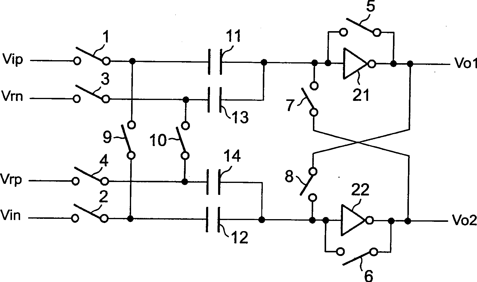
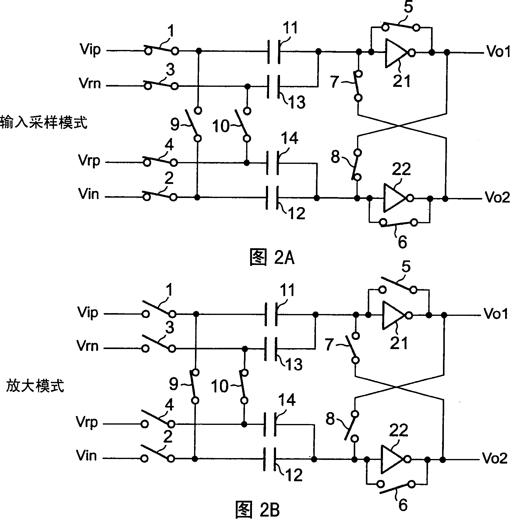
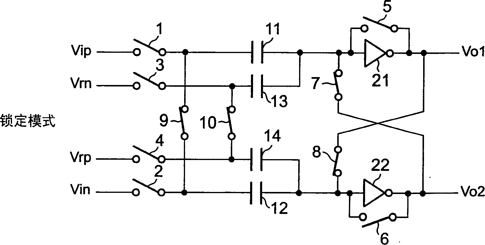
[0041] Next, refer to Figure 1 to Figure 3 The present invention is described.

[0042] In these drawings, numerals 1 to 10 denote on and off switches respectively corresponding to operation modes, numerals 11 to 14 respectively denote capacitors, and numerals 21 and 22 denote a pair of inverters. Furthermore, the symbol Vip represents the positive terminal voltage of the analog input signal, the symbol Vin represents the negative terminal voltage of the analog input signal, the symbol Vrn represents the negative terminal voltage of the reference voltage and the symbol Vrp represents the positive terminal voltage of the reference voltage.

[0043] The switch 1 is connected between the positive terminal voltage Vip of the analog input signal and the capacitor 11, the switch 2 is connected between the negative terminal voltage Vin of the analog input signal and the capacitor 12, and the switch 3 is connected between the negative terminal voltage Vrn of the reference voltage and...


PUM


Abstract

A voltage comparing circuit of the invention includes a first and a second capacitor, terminals on one side of which are respectively connected to a positive side voltage of an analog input signal and a negative side voltage of a reference voltage via a first and a second switch and terminals on other side of which are commonly connected, a third and a fourth capacitor terminals on one side of which are respectively connected to a positive side voltage of the reference voltage and a negative side voltage of the analog input signal via a third and a fourth switch and terminals on other side of which are commonly connected, a first and a second inverter respectively connected to a common connection terminal of the first and the second capacitors and a common connection terminal of the third and the fourth capacitors and connected with a fifth and a sixth switch respectively between input and output terminals thereof, a seventh and an eighth switch respectively connected between the input terminal of the first inverter and the output terminal of the second inverter and between the input terminal of the second inverter and the output terminal of the first inverter, and a ninth and a tenth switch respectively connected between the first capacitor and the fourth capacitor and between the second capacitor and the third capacitor.

Description

technical field [0001] The present invention relates to a voltage comparison circuit, and more particularly to a chopper type voltage comparison circuit used in a high-speed A / D converter or the like. Background technique [0002] The inventors of the present application have proposed a chopper type voltage comparison circuit using an inverter in Japanese Patent No. 3105862. The following will refer to Figure 7 to Figure 10 , describing the published voltage comparator circuit. Figure 7 shows a published voltage comparator circuit, while Figures 8A to 8C show respectively Figure 7 The working states of the input sampling mode, amplification mode and lock mode of the medium voltage comparison circuit. also, Figure 9 is a timing diagram showing the operation of each switch in various modes. In these drawings, numerals 101 to 108 denote switches, numerals 110, 111, 114 and 115 denote capacitors, and numerals 112 and 113 denote inverters. Furthermore, the symbol Vip rep...

Claims


Application Information

Patent Timeline
Patent Type & Authority Applications(China)
IPC IPC(8): H03M1/44G01R19/165H03F3/72H03K5/08H03K5/24
CPCH03F3/72H03K5/249H04N25/78G01R19/165
Inventor 大城户敏夫
Owner NEC ELECTRONICS CORP
Features
  • R&D
  • Intellectual Property
  • Life Sciences
  • Materials
  • Tech Scout
  • Unparalleled Data Quality
  • Higher Quality Content
  • 60% Fewer Hallucinations
Learn More