Washing machine

A technology for washing machines and washing shafts, which is applied in the field of washing machines and can solve problems such as damage to the control drive device 17

Inactive Publication Date: 2003-02-12
PANASONIC CORP
View PDF0 Cites 2 Cited by
  • Summary
  • Abstract
  • Description
  • Claims
  • Application Information

AI Technical Summary

Problems solved by technology

At this time, within the specified stroke, because the sliding member 15 cannot move, the control driving device 17 is locked in the middle, and the control driving device 17 is overloaded, and the control driving device 17 may be damaged.

Method used


Image

  • Washing machine
  • Washing machine
  • Washing machine

Examples


Embodiment 2

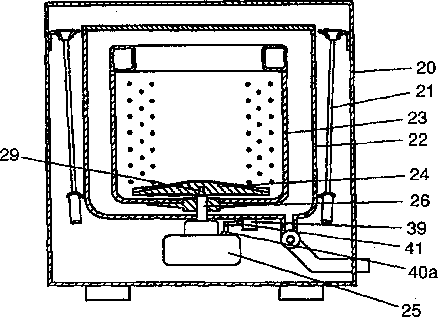
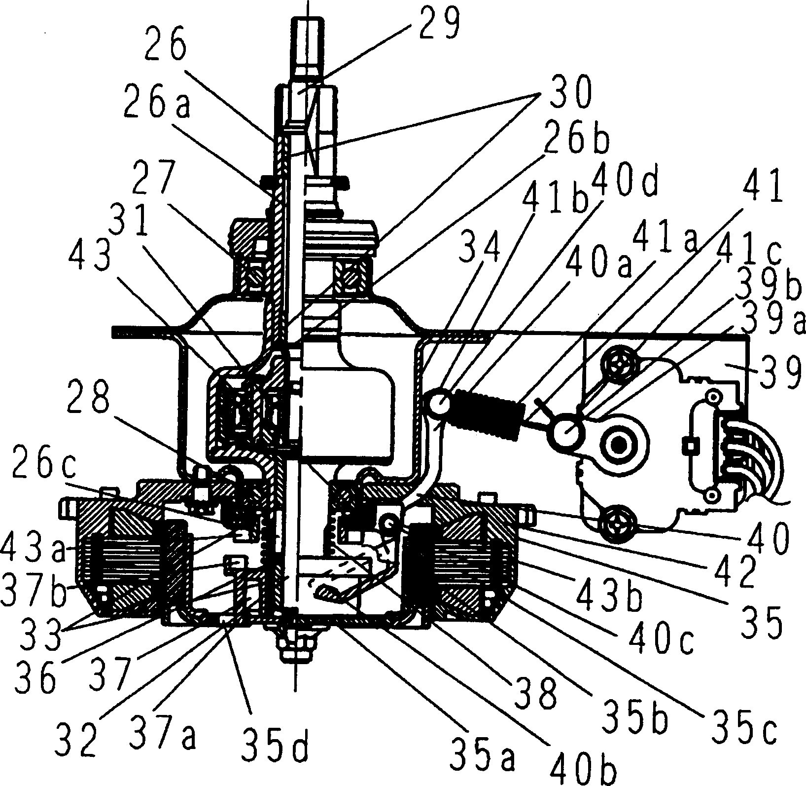
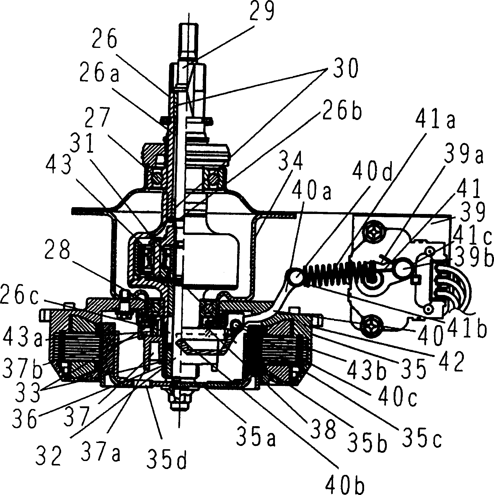
[0040] exist Figure 5 In Fig. 6, the intermediary member 41 is made of a metal wire (wire rod) (spring steel wire, piano wire, etc.), near the end of the clutch lever connecting portion 40a side of the clutch lever 40, there is a spring as an elastic member. The spring structure part 41a. The two ends of the media member 41 are respectively formed with a clutch lever side hook 41b that fits with the clutch lever connection protrusion 40d provided at the clutch lever connection portion 40a and is connected with the drive mechanism at the drive mechanism connection portion 39a. The driving device matched with the protrusion 39b is connected to the hook 41c on one side. The hook 41c on the driving device connection side is rolled into a (substantially) annular linear shape, and the angle between the curled end surface 41d and the straight portion 41e forms a predetermined angle (for example, 0°

[0...


PUM


Abstract

To realize a highly reliable clutch mechanism and safe and sure in change-over operation with a simple configuration by eliminating overloading on a level driving means which is caused by defective engagement in a washing machine provided with an engagement clutch mechanism with the laver driving means such as a geared motor or a solenoid as a driving source. The machine is provided with the lever driving means for operating a clutch lever which vertically slides the slide member for changing-over the transmission of rotation by the driving motor to a dehydrating shaft or a washing shaft by vertical sliding. The clutch lever is connected to the lever driving means with an intermediary member having a spring structure part. Then the level driving means is not overloaded since the spring structure part is extended even the slide member does not move by a prescribed stroke so that a problem of breakage due to a abnormal heating is eliminated.

Description

technical field [0001] The present invention relates to a washing machine for washing, rinsing, and dehydrating clothes. Background technique [0002] Figure 7 The configuration of a conventional washing machine will be described below. In the washing machine main body (frame) 1, a water tank 3 suspended by a suspension rod 2 is installed inside it to prevent dehydration vibration. In the water tank 3, a washing and dehydrating tank 4 is rotatably installed, and at the inner bottom of the washing and dehydrating tank 4, a pulsator 5 for agitating the laundry is rotatably installed. The dehydration shaft 7 is supported by the bearing 6 installed at the bottom of the water tank 3 . The installation of the washing and dehydration tank 4 is substantially coaxial with the dehydration shaft 7 and is fixed on the upper end of the dehydration shaft 7 . The pulsator 5 is installed in the hollow of the dehydration shaft 7 and is substantially coaxial with the dehydration shaft 7 ,...

Claims


Application Information

Patent Timeline
Patent Type & Authority Applications(China)
IPC IPC(8): D06F37/40
Inventor 田原已纪夫赤坂兼一神谷纯司
Owner PANASONIC CORP
Why Eureka
Try Eureka